Hi Nagys,
I was trying to check the protection schematic and the pcb I found something suspicious :
1. The 330pf at D3, D5 was ID C5 but there is a C5 (4.7u) with R13. So I rename the 330pf to C9.
2. The polarized caps have a different convention or Alex has done it the other way round. The hollow rectangle is always the +ve while the solid line (could it be just a thin line or as thick as the rectangle) is the -ve. The main pcb doesn't seems to have problem but the protection circuit is just confusing (seems the caps are all the other way round notationed). Please confirm.
Bigpanda - In the layout, 99% of electrolytic capacitors (in the power supply too) either have the +/- reversed, or the picture/symbol reversed. I already brought that up a few times before. Everything else in the PCB layout is connected correctly, I checked a million times. Those who build this amp should always follow the original schematics, please see them attached. They are correct. For electrolytic capacitors, the empty square is the - and the solid square is the +.
We need to either reverse all the electrolytic capacitors (pictures/symbols and +/-), or not print the silk screen. Otherwise there will always be someone who installs them the wrong way and they'll explode.
We need to either reverse all the electrolytic capacitors (pictures/symbols and +/-), or not print the silk screen. Otherwise there will always be someone who installs them the wrong way and they'll explode.
Attachments
Hi Nagys,
I am not going to agrue with the convention because it is too old a story and it had been done too many times in this forum. As long as we use the same convention all along the same schematic or the same set of schematics of a project, I don't think we should have a problem. When I do my schematics and pcb, I will always put a '+' sign to make things clear (just like we got a '-' sign on every polarized cap we bought). That would eliminate any mis-convention.
In the main board schematic, I can use the one at the Vcc's to follow the designer's convention but as for the protection schematic, I am getting confused (sorry about my limited knowledge on this).
I had been reading all post for this thread and I don't know if I might have been taking a nap and miss some part you said you have state about the 'wrong convention'.
If your hand drawn schematics (main and prot that you have posted in very early posts) are correct, I will follow that onto the pcb (at least for the polarities of the ele caps).
I will try to post a final GB status report tomorrow.
Bigpanda - Sorry for the confusion. In Alex's PCB, all the electrolytic capacitors are shown CORRECTLY, +/-, including in the protection circuit. Please do not change anything ") I forgot this is a European schematic, as well as my hand drawn one. In Europe, the - is either a line, or a solid square and the + is the empty square. I've been working on a few schematics here and got it mixed up with the American ones. Again, all the +/- are correct in Alex's layout Sorry for the confusion Alex! I also checked once again all the traces and connections, everything looks good.
I forgot this is a European schematic, as well as my hand drawn one. In Europe, the - is either a line, or a solid square and the + is the empty square. I've been working on a few schematics here and got it mixed up with the American ones. Again, all the +/- are correct in Alex's layout Sorry for the confusion Alex! I also checked once again all the traces and connections, everything looks good.
I forgot this is a European schematic, as well as my hand drawn one. In Europe, the - is either a line, or a solid square and the + is the empty square. I've been working on a few schematics here and got it mixed up with the American ones. Again, all the +/- are correct in Alex's layout Sorry for the confusion Alex! I also checked once again all the traces and connections, everything looks good.where is the arithmetic?
What are the operating conditions you have assumed?
How can a builder with little experience check if your assumptions meet his operating criteria?
You should have quoted:
a 230:60+60Vac 5% regulation transformer on a 254Vac supply will give ~97.9Vdc
I can confirm your arithmetic seems to be correct, but I had to make a number of assumptions for what you had used to determine the modeled DC voltage.
I agree totally with your sentiment, but here in the UK at least the nominal 240 V mains was given assymetric limits to harmonise it a bit with global and continental stds, they reset all the tap jumper transformers for 230 V mains within a week of the new regs... as it gave them more "free" capacity...
Wrinkle.
Hi all group buyers,
A new updated status report is posted in :
http://www.diyaudio.com/forums/group-buys/175296-pcb-order-goldmun-clone-20.html#post2356190
A new updated status report is posted in :
http://www.diyaudio.com/forums/group-buys/175296-pcb-order-goldmun-clone-20.html#post2356190
Parts to the Golmund clone. GB?
Who can imagine to take responsibility for a GB for parts to "our" Golmund clone?
I see tree costly parts where it might be possible to achieve advantageous current prices by walking together on procurement.
Output devices
The large kondesatorene C31/C34
Relay.
Other suggestions?
Eivind Stillingen
Who can imagine to take responsibility for a GB for parts to "our" Golmund clone?
I see tree costly parts where it might be possible to achieve advantageous current prices by walking together on procurement.
Output devices
The large kondesatorene C31/C34
Relay.
Other suggestions?
Eivind Stillingen
Hello!!
How is this amp compared to leach 4.5, in quality?
Thanks.
It is the best sounding amp ever heard, so why bother asking?

Hello!!
How is this amp compared to leach 4.5, in quality?
Thanks.
Comparing a good bipolar vs a good mosfet is like comparing an orange to an apple. Each amp has its own lovers. But I'll take an apple any day
Comparing a good bipolar vs a good mosfet is like comparing an orange to an apple. Each amp has its own lovers. But I'll take an apple any day
Although my username may leed folks to think otherwise, frankly I could not agree more! I may just have to simulate this with a bipolar output section and perhaps someday build it up and give it a shot.
If folks really want to taste a good mosfet design, I would urge them to the Nelson Pass portion of DIY Audio.

The ultimate sounding amplifier = holy grail? I'm happy Nagy found his favourite amplifier and I think it is grand that he took the time to share his feelings here about it. If you're sharing ideas and trading information, what could be more fun? Geez, if all these builders are getting a billion dollar amp for under a thousand bucks or so, then people should line up and kiss his _ _ _.
DIY =

Cheers to all of you; the good, the bad and the ugly!
Last edited:
No, this topology is indeed very favorable for the lateral, but bipolars have their own favorable topologies. If you want bipolar amp with similar topology, try Ostripper's design.I may just have to simulate this with a bipolar output section and perhaps someday build it up and give it a shot.
Unfortunately they are class A, and complex (yes, the X topology). Who wants 100W amp in class A? Not meIf folks really want to taste a good mosfet design, I would urge them to the Nelson Pass portion of DIY Audio.
But I wish the master would lay his hand on class-B mosfet someday. But not Citation 12 The ultimate sounding amplifier = holy grail?
What is the ultimate sounding capacitor? What is the ultimate sounding transistor? Such is the ultimate sounding amplifier.
By Jay - No, this topology is indeed very favorable for the lateral, but bipolars have their own favorable topologies. If you want bipolar amp with similar topology, try Ostripper's design.
Almost ready , even prototyped. when I get my sk134/j49's (hitachi's), I will even give them a "run". This topology , (with drivers) actually is at home with either BJT's or mosfets. With laterals , one could even leave out the drivers and "crank up" the VAS current , driving the laterals "direct".
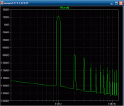
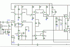
With transitional miller compensation (TMC) .. BJT's can even beat laterals. (below- 1). Just for comparison , the circuit can use LSK170/389 for LTP or MPSA18's. I aim to BEAT the goldmund .. period. (pix2/3). Keentoken has the same goal. Compared to the original w/MPSA's, the distortion components are the same , just 10 - 15 db lower. No one would make any money on this one either , 20 year+ service life is expected.
OS
Attachments
- Home
- Amplifiers
- Solid State
- The Very Best Amplifier I Have Ever Heard!!!!