Well I finally got some measurements that I'm confident in using in my sims.
I took measurements outside at 66cm which are almost good enough on their own. I then took nearfiled measurements and merged them in with the 66cm measurements using the procedures that Jeff Bagby and Charlie Laub have developed. FRD Blender and Minimum Phase Extractor
Those measurements were taken on the tweeter axis for the MTM and on axis with the woofer for the woofer measurement.
I then took meausrements of each of the woofer and MTM at a distance of 1.6M with the mic positioned half way between the woofer and the MTM's tweeter. finally I took measurements with both drivers running (one with woofer inverted, one without).
I extracted the minimum phase for the individual 1.6M measurements and then loaded into PCD with the combined measurement as an overlay. This allowed me to fine tune the Z offset and vertical offset (horizontal didn't matter as it was pretty close to center)
Once I had these offsets, loading in the individual 66cm measurements resulted in a sim VERY close to the 1.6M measurement.
This proved the approach should work.
I then loaded the blended measurements into PCD, set the offsets so that they represented my listening position (ie on tweeter axis and at 3M) and started to work on the crossover.
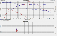
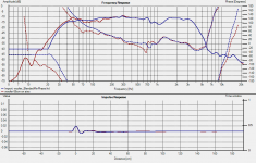
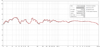
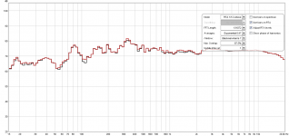
Below are my various measurements. I'll do a separate post about the PCD exercise as this one is already long!
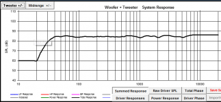
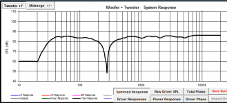
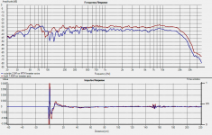
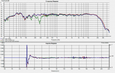
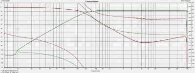
The two attachments show the blue (blended response) compared to the measurement at 66cm. This shows (particularly in the MTM example) that the method of blending the nearfield response is very accurate. The baffle step modeling part is what makes the difference. The woofer result looks a bit off compared to the measurement but I'm pretty sure that was due to the measurement position as it would have been getting some reinforcment from the roughly 0.5M of wall below it (it was sitting on the edge of my deck).
Next post I'll show what I have done with PCD.
Tony.
I took measurements outside at 66cm which are almost good enough on their own. I then took nearfiled measurements and merged them in with the 66cm measurements using the procedures that Jeff Bagby and Charlie Laub have developed. FRD Blender and Minimum Phase Extractor
Those measurements were taken on the tweeter axis for the MTM and on axis with the woofer for the woofer measurement.
I then took meausrements of each of the woofer and MTM at a distance of 1.6M with the mic positioned half way between the woofer and the MTM's tweeter. finally I took measurements with both drivers running (one with woofer inverted, one without).
I extracted the minimum phase for the individual 1.6M measurements and then loaded into PCD with the combined measurement as an overlay. This allowed me to fine tune the Z offset and vertical offset (horizontal didn't matter as it was pretty close to center)
Once I had these offsets, loading in the individual 66cm measurements resulted in a sim VERY close to the 1.6M measurement.
This proved the approach should work.
I then loaded the blended measurements into PCD, set the offsets so that they represented my listening position (ie on tweeter axis and at 3M) and started to work on the crossover.
Below are my various measurements. I'll do a separate post about the PCD exercise as this one is already long!
The two attachments show the blue (blended response) compared to the measurement at 66cm. This shows (particularly in the MTM example) that the method of blending the nearfield response is very accurate. The baffle step modeling part is what makes the difference. The woofer result looks a bit off compared to the measurement but I'm pretty sure that was due to the measurement position as it would have been getting some reinforcment from the roughly 0.5M of wall below it (it was sitting on the edge of my deck).
Next post I'll show what I have done with PCD.
Tony.
Attachments
I started out the wrong way with PCD. I started to do the modeling of the crossover to get the best result, right from the start. What I should have done was get something ok, then implement it in the synergy and see how it compared.
What I found was that my sim wasn't matching my actual measured results so well to start off with. So what I did was a loopback measurement of my sound card and used that in the sim for the tweeter and woofer responses. I could do one driver at a time and export the frd from PCD then compare it to the actual measurement of the synergy.
I found I needed to model with a load resistance of 100Ohms for the low pass (scaling caps and coils appropriately in the sim) That results in an almost exact match for sim and actual realized performance.
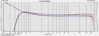
The high pass was a little trickier. I was using a load resistance of 6.2k and found the best match when I upped this in the sim to 6.65K This resulted in curves that were within 0.1db which I think is more than acceptable")
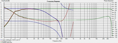
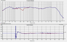
Screen shots below show the LP and HP sim versus actual measurements of the realised circuit.
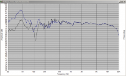
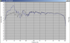
The third and fourth screenshots show the simulated (quasi anechoic) response of the combined MTM's and woofer.
The passive LP that is simulated by the synergy is 220mH 7.5uF 56mH (driving 100 ohm load). This translates to 22k 7.5l and 5.6K resistors in the synergy circuit.
The passive HP that is simulated by the synergy is 47nf 2.4H 200nf (driving 6.2K load) The caps remain as above and the 2.4H coil is replaced by a 2.4K resistor.
So for this result I used 3rd order for both LP and HP circuits. 2nd Order is easily done by replacing the second cap or resistor (simulating the coil) with a shunt.
The realisation is almost exactly matching the performance of a perfect passive implementation (perfect as in perfect caps and coils).
I've stopped trying to track down the source of noise in the lp as it is at such a low level I do not believe it will be a problem.
Next step is to actually try it out with some music (only in mono as I only have one board built) and do some in room measurements to see what I get.
Tony.
What I found was that my sim wasn't matching my actual measured results so well to start off with. So what I did was a loopback measurement of my sound card and used that in the sim for the tweeter and woofer responses. I could do one driver at a time and export the frd from PCD then compare it to the actual measurement of the synergy.
I found I needed to model with a load resistance of 100Ohms for the low pass (scaling caps and coils appropriately in the sim) That results in an almost exact match for sim and actual realized performance.
The high pass was a little trickier. I was using a load resistance of 6.2k and found the best match when I upped this in the sim to 6.65K This resulted in curves that were within 0.1db which I think is more than acceptable
Screen shots below show the LP and HP sim versus actual measurements of the realised circuit.
The third and fourth screenshots show the simulated (quasi anechoic) response of the combined MTM's and woofer.
The passive LP that is simulated by the synergy is 220mH 7.5uF 56mH (driving 100 ohm load). This translates to 22k 7.5l and 5.6K resistors in the synergy circuit.
The passive HP that is simulated by the synergy is 47nf 2.4H 200nf (driving 6.2K load) The caps remain as above and the 2.4H coil is replaced by a 2.4K resistor.
So for this result I used 3rd order for both LP and HP circuits. 2nd Order is easily done by replacing the second cap or resistor (simulating the coil) with a shunt.
The realisation is almost exactly matching the performance of a perfect passive implementation (perfect as in perfect caps and coils).
I've stopped trying to track down the source of noise in the lp as it is at such a low level I do not believe it will be a problem.
Next step is to actually try it out with some music (only in mono as I only have one board built) and do some in room measurements to see what I get.
Tony.
Attachments
Good news. The listening test (mono) is a success. Last time sounded off, this time I can't pick any problems
Everything is sitting out of the case with long leads and there is some RF pickup (which is what I think the noise in the higher frequencies in the LP section are) touching the volume control on my B1 preamp tunes into some radio station!!
Will also do some pink noise in room measurements to see what's what, but I think I'm finally ready to build a stereo pair.
Tony.
Thanks Fred. I tried to do some in room measurements yesterday to confirm what I was hearing, but my gear just wouldn't play ball. There's something wrong with either my mic preamp or my sound card, and I'll need to do some investigation to work out where the issue is.
Anyone is most welcome to give it a go!! I'd offered some boards to Mondo and James but they haven't taken up the offer. If you would like a stereo pair let me know and I can send you a couple.
Note these were the first prototype boards so there are a couple of things not quite right, but they are minor. The two main issues were the +10V hole pad being offset and shorting to the ground plane (which I have fixed with the dremel on all boards) and no provision for resistor to ground on input (I just soldered the required resistor to the reverse side of the board from input hot to ground.
I think I have also added a couple of stability caps on the reverse side of the board, though that may have been because I didn't have surface mount ones in the required value.
If I were to do a 2nd revision board those things would be fixed, I'd also probably try and accomodate two caps for each of the two series cap's in the HP section to make it easier to get bigger or unusual values. For the 2nd cap I needed 200nH which I did by using two 100nH MKP1387's one in the correct position and the other soldered on the back.
I probably should also look at rf filtering on the input!
Tony.
OK I've got in room and outside measurements. The in room do not tell me that much (other than there is more bass ) The room modes dominate at the lower frequencies and I couldn't get any decent indication as to whether my phase was matching ok or not. So today I wanted to make sure of it and did some measurements outside. The in room measurements were done using the MMM method.
The measurements at 2.5 and 3.0M had too many reflections so were not very conclusive. I measured at 1.45M which was just earlier than the first reflection and when mesauring mid way between the woofer and tweeter the phase matching was good enough for me to be satisfied.
Attached are some images of the measurements.
The first shows the difference between just the right mtm playing in room and with right MTM and woofer. You can see how big the room node at around 40Hz is! The measurement of the left side is much tamer The second shows left vs right.
The third shows the comparison of outside measurements at 2.5M and 1.45M on axis with the tweeter of the MTM
The fourth shows the 1.45M measurement compared to same but with woofer reversed. The non-reverse null measures are 1/16th octave smoothed. the reverse null one is 1/48th octave smoothed, The raw measurement shows the null around 5db deeper.
The 5th measurement was taken at 0.8M midway between the woofer and tweeter. Note that this is way off axis vertically for the MTM, but shows very flat response through the crossover region. The reverse null isn't as good as at 1.45M but I suspect that is due to being too close.
Tony.
) The room modes dominate at the lower frequencies and I couldn't get any decent indication as to whether my phase was matching ok or not. So today I wanted to make sure of it and did some measurements outside. The in room measurements were done using the MMM method. The measurements at 2.5 and 3.0M had too many reflections so were not very conclusive. I measured at 1.45M which was just earlier than the first reflection and when mesauring mid way between the woofer and tweeter the phase matching was good enough for me to be satisfied.
Attached are some images of the measurements.
The first shows the difference between just the right mtm playing in room and with right MTM and woofer. You can see how big the room node at around 40Hz is! The measurement of the left side is much tamer The second shows left vs right.
The third shows the comparison of outside measurements at 2.5M and 1.45M on axis with the tweeter of the MTM
The fourth shows the 1.45M measurement compared to same but with woofer reversed. The non-reverse null measures are 1/16th octave smoothed. the reverse null one is 1/48th octave smoothed, The raw measurement shows the null around 5db deeper.
The 5th measurement was taken at 0.8M midway between the woofer and tweeter. Note that this is way off axis vertically for the MTM, but shows very flat response through the crossover region. The reverse null isn't as good as at 1.45M but I suspect that is due to being too close.
Tony.
Attachments
Last edited:
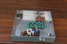
OK well it has been a year since that post. Time flies.... I decided in Dec I was pretty disapointed that I hadn't built the final versions and ordered the parts. I started to put it together yesterday. Basically doing the same filters as the above prototype.
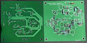
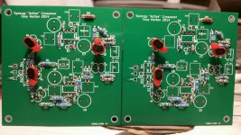
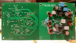
A pic of the progress so far.
I decided to try out the LM4562 hoping it might help with the "noise" problem in the stop band of the LP filter. It didn't make any difference, which was a bit disapointing, That got me searching once again for info on FDNR's and I stumbled upon an article I hadn't seen before. It has FDNR's with single opamps, which may work better in this application. I did a sim and I can get it to work (in the sim) but the values for the resistors that simulate the coils were wildly different to the values that are predicted. I'll bread board something and see how it behaves in real life, but not until after I have this one installed and running!!
A synergy 2.0 may be forthcoming, hopefully it won't take another 6 years One of the best things about using the single opamp FDNR's (assuming you can tweak the values until it meets your target curve) would be that a single opamp could do 2nd, 3rd, 4th, and 5th order electrical filters just by adding passive components (or shunting them). I really like the idea of that!! The current one can do 2nd or 3rd order electrical. I believe that you can also do the same for the HP circuit, though I haven't looked closely at that yet.
After just having matched 10 pairs of 2sk170's for the two boards, I'm also thinking that a transistor based buffer (or god forbid an opamp one) may be more practical.
It's ok for just me, but If I can get a board together that has good performance and is as flexible as having all those orders possible then I think maybe some people would be interested in it, and they might not want to go to the level of trouble that I have with this one!
Anyway. Hopefully I've got the momentum to get these current boards finished and installed into my system! It's been a long time coming!!!
Tony.
A pic of the progress so far.
I decided to try out the LM4562 hoping it might help with the "noise" problem in the stop band of the LP filter. It didn't make any difference, which was a bit disapointing, That got me searching once again for info on FDNR's and I stumbled upon an article I hadn't seen before. It has FDNR's with single opamps, which may work better in this application. I did a sim and I can get it to work (in the sim) but the values for the resistors that simulate the coils were wildly different to the values that are predicted. I'll bread board something and see how it behaves in real life, but not until after I have this one installed and running!!
A synergy 2.0 may be forthcoming, hopefully it won't take another 6 years
One of the best things about using the single opamp FDNR's (assuming you can tweak the values until it meets your target curve) would be that a single opamp could do 2nd, 3rd, 4th, and 5th order electrical filters just by adding passive components (or shunting them). I really like the idea of that!! The current one can do 2nd or 3rd order electrical. I believe that you can also do the same for the HP circuit, though I haven't looked closely at that yet. After just having matched 10 pairs of 2sk170's for the two boards, I'm also thinking that a transistor based buffer (or god forbid an opamp one) may be more practical.
It's ok for just me, but If I can get a board together that has good performance and is as flexible as having all those orders possible then I think maybe some people would be interested in it, and they might not want to go to the level of trouble that I have with this one!
Anyway. Hopefully I've got the momentum to get these current boards finished and installed into my system! It's been a long time coming!!!
Tony.
Attachments
The Boards have been completed, tested and listening test performed. The result is a resounding success
There is still some noise in the low pass filter, but as it in the frequency region that is at least 60db down I really don't think it is going to be an issue.
Removing the sub 270 Hz duty from the MTM's has really cleaned up the sound. "Dense" music is finally listenable at higher volumes. White stripes Elephant now plays without a desire to drop the volume or turn it off completely!
Pink noise and RTA tests in room show that there is a lot better bass than before (and it is really noticable on certain music!)
The next major change will be creation of new cabinets for the 10" vifa's. There are some resonances that are excited by certain notes, this has always been the plan. A new cabinet will also allow a much better integration of the drives, as at the moment the CTC distance between the woofer and the lower M is quite a lot (around 700mm I think) Despite this though the sound integrate well at the listening position
The boards have not made their way into their case yet. Tests were performed open on the carpet being fed by batteries, but it won't be too long before they are installed as the improvment in the sound is large (and I needed to pack up once I was done testing).
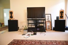
Some more pics attached.
1st the finished (actually nearly there were a couple of components added on the reverse of the board) boards.
2nd The test of the filters.
3rd the actual listening test
4th in room pink noise with rta with the MTM's + 10" vifas
5th in room pink noise with rta with just the MTM's
Note the reason the level is higher with just the MTM's is two fold. Firstly because there is approximately 4db attenuation on the high pass to match with the woofers, secondly because the amp driving the MTM's has 30 X gain, whereas the amp driving the woofers has 10 X gain, so there is even more attenuation in the Synergy to deal with that. The MTM only was running direct on the higher gain amp, all other settings the same.
I'd like to change the gain on the Lm3886 down to 20 X to match the other amp but it is not going to happen, the last image may give a clue as to why
Tony.
There is still some noise in the low pass filter, but as it in the frequency region that is at least 60db down I really don't think it is going to be an issue.
Removing the sub 270 Hz duty from the MTM's has really cleaned up the sound. "Dense" music is finally listenable at higher volumes. White stripes Elephant now plays without a desire to drop the volume or turn it off completely!
Pink noise and RTA tests in room show that there is a lot better bass than before (and it is really noticable on certain music!)
The next major change will be creation of new cabinets for the 10" vifa's. There are some resonances that are excited by certain notes, this has always been the plan. A new cabinet will also allow a much better integration of the drives, as at the moment the CTC distance between the woofer and the lower M is quite a lot (around 700mm I think) Despite this though the sound integrate well at the listening position
The boards have not made their way into their case yet. Tests were performed open on the carpet being fed by batteries, but it won't be too long before they are installed as the improvment in the sound is large (and I needed to pack up once I was done testing).
Some more pics attached.
1st the finished (actually nearly there were a couple of components added on the reverse of the board) boards.
2nd The test of the filters.
3rd the actual listening test
4th in room pink noise with rta with the MTM's + 10" vifas
5th in room pink noise with rta with just the MTM's
Note the reason the level is higher with just the MTM's is two fold. Firstly because there is approximately 4db attenuation on the high pass to match with the woofers, secondly because the amp driving the MTM's has 30 X gain, whereas the amp driving the woofers has 10 X gain, so there is even more attenuation in the Synergy to deal with that. The MTM only was running direct on the higher gain amp, all other settings the same.
I'd like to change the gain on the Lm3886 down to 20 X to match the other amp but it is not going to happen, the last image may give a clue as to why
Tony.
Attachments
It's a bit of a marathon Andrew! It's evolved since the original blog post http://www.diyaudio.com/forums/blogs/wintermute/245-synergy-active-crossover.html But the blog entry is probably the best place to start to understand the original design philosophy. The implemented version actually is using 3rd order electrical filters with custom slopes to arrive at 4th order bessel acoustic slopes.
The fact that I can simulate a passive filter in something like speakerworkshop, xsim or PCD and then implement that exact same transfer function actively was very appealing, and has finally worked out well.
Tony.
It's evolved since the original blog post http://www.diyaudio.com/forums/blogs/wintermute/245-synergy-active-crossover.html But the blog entry is probably the best place to start to understand the original design philosophy. The implemented version actually is using 3rd order electrical filters with custom slopes to arrive at 4th order bessel acoustic slopes. The fact that I can simulate a passive filter in something like speakerworkshop, xsim or PCD and then implement that exact same transfer function actively was very appealing, and has finally worked out well.
Tony.
The original post1 shows a CL 2pole filter.
Is there a way to calculate the Fr and Q of this filter?
The latest post171 shows a CLCR 3pole filter.
Is there a way to calculate the Fr and Q of this filter?
How?
How did you arrange for the acoustic roll-off of the upper driver to coincide with the Fr of the electrical filter.
Is there a complementary single pole roll-off for the lower driver to make the combined 3pole+acoustic equal a 4pole filter?
Is there a way to calculate the Fr and Q of this filter?
The latest post171 shows a CLCR 3pole filter.
Is there a way to calculate the Fr and Q of this filter?
How?
How did you arrange for the acoustic roll-off of the upper driver to coincide with the Fr of the electrical filter.
Is there a complementary single pole roll-off for the lower driver to make the combined 3pole+acoustic equal a 4pole filter?
Last edited:
Hi Andrew, that's the beauty of this filter. You design it passively just as you would if you were doing a CL a CLC a LC or LCL
For the high pass, you can control the values for the first C by changing the load resistance (I found that I got best distortion performance in the sims using 47nF there).
For the low pass the filter is calculated with a load of 1 ohm (though I found in sims it was better to use 100 ohms and scale the other components accordingly).
To check the performance of the active implementation I compare against the passive design in ltspice. Some adjustment of values from the theoretical may be necessary to get the same slope.
When I got to the point of doing accoustic slopes I simmed the crossover passively (I think I used speaker workshop but I may have used PCD). For the driver impedance I put in a dummy impedance file with constant impedance that matched the value of the load for the high or low pass filters, in the case of the HP this is 6.19k for the low pass I found 100 ohms worked well (and made component value scaling easy).
When I had a passive filter that worked well with the measured driver responses I then simulated that passive in spice, and converted the coils to resistors and the cap to the D value in the fdnr (I'm struggling to remember how the coil value is calculated for the high pass but it should be in here somewhere)
There is a post earlier which I'll have to find that explains how I went about matching the simmed filter response to the actual realised response. The high pass from memory required some adjustment to the load resistance to get an accurate match.
here is one post discussing the passive sim http://www.diyaudio.com/forums/analog-line-level/164886-synergy-active-crossover-5.html#post3994440
gotta run train is getting in.
edit: this is the post talking about "calibration" of sim to reality. http://www.diyaudio.com/forums/analog-line-level/164886-synergy-active-crossover-6.html#post4172560
Tony.
For the high pass, you can control the values for the first C by changing the load resistance (I found that I got best distortion performance in the sims using 47nF there).
For the low pass the filter is calculated with a load of 1 ohm (though I found in sims it was better to use 100 ohms and scale the other components accordingly).
To check the performance of the active implementation I compare against the passive design in ltspice. Some adjustment of values from the theoretical may be necessary to get the same slope.
When I got to the point of doing accoustic slopes I simmed the crossover passively (I think I used speaker workshop but I may have used PCD). For the driver impedance I put in a dummy impedance file with constant impedance that matched the value of the load for the high or low pass filters, in the case of the HP this is 6.19k for the low pass I found 100 ohms worked well (and made component value scaling easy).
When I had a passive filter that worked well with the measured driver responses I then simulated that passive in spice, and converted the coils to resistors and the cap to the D value in the fdnr (I'm struggling to remember how the coil value is calculated for the high pass but it should be in here somewhere
) There is a post earlier which I'll have to find that explains how I went about matching the simmed filter response to the actual realised response. The high pass from memory required some adjustment to the load resistance to get an accurate match.
here is one post discussing the passive sim http://www.diyaudio.com/forums/analog-line-level/164886-synergy-active-crossover-5.html#post3994440
gotta run train is getting in.
edit: this is the post talking about "calibration" of sim to reality. http://www.diyaudio.com/forums/analog-line-level/164886-synergy-active-crossover-6.html#post4172560
Tony.
Last edited:
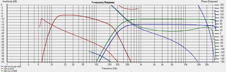
I've done some objective measurements tonight, as I had not checked the relative levels on the LP and HP (the LP by design is supposed to be 3db higher than the HP).
It was spot on (well actually the bass was 0.1db lower than it was supposed to be) so I'm not touching the pots.... considering the amps had different amounts of gain and I needed to cut 3db I'm rather surprised the factory setting for BOTH pots was exactly right for my situation. The reality was I needed 6.5db attenuation on the HP so that is close to the middle of the pot
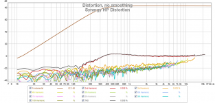
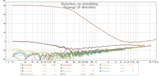
Attached is a plot showing the measurements through the amps with 8 ohm dummy load. The blue curve is showing the HP through the two different amps. The blue is my mosfet amp which has a slight rolloff (0.5db at 20Khz) which starts at about 5Khz.
The distortion measurements I think are pretty decent. max around 0.01% distortion (predominantly 2nd harmonic, which is what the sims predicted (albeit over optimistically lower). This was measured direct, not through the amp. The LP thd figures in the legend are screwed up no doubt because it was centering around 1Khz.
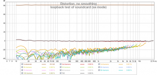
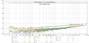
I just remembered that my focusrite 2i2 does fairly poorly distortion wise into SE so I just did some loopback mesurements. the fourth is SE loopback and the 5th is balanced loopback. As you can see even in the SE loopback the performance is very similar, so take the above measurements with a grain of salt. It is possible that the distortion performance is actually better.
Tony.
It was spot on (well actually the bass was 0.1db lower than it was supposed to be) so I'm not touching the pots.... considering the amps had different amounts of gain and I needed to cut 3db I'm rather surprised the factory setting for BOTH pots was exactly right for my situation. The reality was I needed 6.5db attenuation on the HP so that is close to the middle of the pot
Attached is a plot showing the measurements through the amps with 8 ohm dummy load. The blue curve is showing the HP through the two different amps. The blue is my mosfet amp which has a slight rolloff (0.5db at 20Khz) which starts at about 5Khz.
The distortion measurements I think are pretty decent. max around 0.01% distortion (predominantly 2nd harmonic, which is what the sims predicted (albeit over optimistically lower). This was measured direct, not through the amp. The LP thd figures in the legend are screwed up no doubt because it was centering around 1Khz.
I just remembered that my focusrite 2i2 does fairly poorly distortion wise into SE so I just did some loopback mesurements. the fourth is SE loopback and the 5th is balanced loopback. As you can see even in the SE loopback the performance is very similar, so take the above measurements with a grain of salt. It is possible that the distortion performance is actually better.
Tony.
Attachments
The high pass was a little trickier. I was using a load resistance of 6.2k and found the best match when I upped this in the sim to 6.65K This resulted in curves that were within 0.1db which I think is more than acceptable
It would seem that the reason I had to model with 6.65K is because that is what value resistor I actually soldered to the board
I was putting together some info to explain how I'd done the sims and exported the high pass sim to compare to my latest measurements and it didn't match (was out by about 1/2 db)
I haven't actually checked the board yet (not home) but when I put a 6.19K load into the PCD sim and exported the curve, it is an exact match for the real world implementation.
This is rather annoying as I now have to get some 6.65K resistors if I want to have the original intended transfer function (since I used 0.1% for everything in the filter circuit I can't just get it from Jaycar), and I don't want to pay $10 shipping for a couple of resistors. argghh. I guess I should just put a couple of 1% resistors in (I must have some of that value) and be done with it.
The upside is that for both the LP and the HP the PCD sim matches perfectly the realised transfer funtion. What I also discovered was that the LTSpice curves Do not! I spent a lot of time in spice comparing passive to active transfer functions, in reality neither matches the curves from PCD or the implementation. I never would have got the circuit working without spice, but don't rely on it for working out the transfer functions!! Just trust that if you use close tolerance resistors, the circuit will behave exactly like a passive network using ideal (ie 0 esr caps 0 dcr coils) components.
Tony.
Thanks Andrew. The plot thickens somewhat. I checked the prototype board and it has 6.19K. Now I don't know whether I changed it at some point or whether there was something else strange going on.
The one difference is that I was using opa2134's in the prototype and LM4562's in the final, I should pop an OPA2134 in and remeasure and see if there is any difference (I suspect that there won't be). The proto board is currently unusable as I took the rca's off it to use on the finished board for testing
After revisiting the original sim I think I could have done better. I might have a play with different load values and see how it looks. If I'm to change it I might as well improve it if possible!
Tony.
I decided to just leave the resistors. I'm happy enough with the sound and revisiting the sims actually showed that the phase alignment was actually a bit better with the lower value, even if there is a bit of a 1/2 db dip (which coincidentally is in an area where there was a bit of a peak in the response in room before.
It's all in the box and probably won't be touched (except maybe for some more distortion tests once I have a balanced to single ended converter for my focusrite 2i2.
I will also do some breadboard circuits of an alternate FDNR I've recently discovered, as they look like they could perform better, and are also simpler.
I'll put up some stuff on doing the sims as well whilst it is still fresh, as I struggled to remember what I had done before when looking at it again recently.
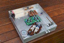
Pics attached of everything in the box. The DCB1 that is on the switch and volume board, is now disconnected. I toyed with putting in a relay to switch the high pass output between the crossover and straight pass through but just decided to disconnect it.
This and the YARPS power supply that is powering it, are my first from scratch designs, so pretty happy that it has finally come to fruition, and that it is working properly and is an enhancement to my system!
Tony.
It's all in the box and probably won't be touched (except maybe for some more distortion tests once I have a balanced to single ended converter for my focusrite 2i2.
I will also do some breadboard circuits of an alternate FDNR I've recently discovered, as they look like they could perform better, and are also simpler.
I'll put up some stuff on doing the sims as well whilst it is still fresh, as I struggled to remember what I had done before when looking at it again recently.
Pics attached of everything in the box. The DCB1 that is on the switch and volume board, is now disconnected. I toyed with putting in a relay to switch the high pass output between the crossover and straight pass through but just decided to disconnect it.
This and the YARPS power supply that is powering it, are my first from scratch designs, so pretty happy that it has finally come to fruition, and that it is working properly and is an enhancement to my system!
Tony.
Attachments
OK so I've zipped up the spice files for the final implementation and also the PCD csp file and the various frd and zma files I used. Both attached.
The spice should uncompress into a directory and should be fully self contained, ie it should run provided you open it from the directory, you don't need to install any of the models.
I originally thought (incorrectly) that by modelling the circuit passively in spice I could compare that to the circuit output and tweak to get the closest match to the passive implementation. This was in fact a mistake. Neither the passive or the active simulation in spice accurately models the slope. I was wasting my time trying to get the two to match. What spice was (I think) valuable for was working out what load resistor to use for the high pass. Actually in the end I decided I wanted the first cap to be 47nF and adjusted the load resistor to allow me to get a target curve that worked with 47nF for the first cap.
What I ended up doing was the simulation in PCD (passive crossover designer)
I arrived at target filters using an online calculator This one Crossover Design Chart and Inductance vs. Frequency Calculator(Low-pass)
For the high pass I put in my load resistor value (6.19K in this case) and target of third order electrical at 270 Hz (as a starting point) I put these values it gave for caps and coils into PCD.
I also put the speaker Z and Y offsets into PCD.
I took an impedance file and loaded it into excell, I changed the first impedance value to 6190 and did a fill down to replace the values for all the other cells.
I similarly put zero into the phase column and filled down. This then became my High pass ZMA file.
For the Low pass I found I needed to sim with a value of 100 ohms for the sim (however the FDNR requires values based on a load of 1 ohm). The ZMA file was created the same way as the HP one but with 100 as the impedance value.
The Low pass filter was calculated using the online calculator with a load of 1 ohm.
The coil and cap values were then scaled by 100 to get the values to enter into PCD. Coil is multiplied by 100, cap divided by 100.
To check my results I did a loopback measurement on my sound card and used that as the FRD file for woofer and MTM in PCD. The resulting filter transfer functions were saved as frd files.
I implemented this on the synergy board, and did measurements of the output of both low and high pass with holm impulse. I then imported the saved PCD transfer functions into holm impulse and compared the results. They were basically identical.
It is important not to put any ESR in the coils or caps in the sim.
I then used the actual measured response of the woofers and MTM's in PCD and adjusted the values of coils and caps until I got the best response. These final values were the values I used for the realization of the circuit.
edit: note that the value of the resistor in the HP GIC can be scaled up or down provided you also do the oposite for one of the 10K resistors. For instance the value of 2.43K (for the 2430 mH coil) can be changed to 24.3k and one of the 10K resistors changed to 1K. The overall effect will be the same. This may be necessary if a smaller inductance is required. With 10K resistors for all the other resistors, the value of the coil in mH translates to the value of the resistor in ohms.
Tony.
Attachments
Last edited:
I thought I would also mention that when you scale the caps and coils in the sim by 100, that it makes it fairly easy to convert the values to the resistor values for the actual implementation.
The resistor that becomes the "cap" in the FDNR is basically the value in uF in K
The resistors that become the "coils" in the FDNR are the values in mH divided by 10 in K
Tony.
The resistor that becomes the "cap" in the FDNR is basically the value in uF in K
The resistors that become the "coils" in the FDNR are the values in mH divided by 10 in K
Tony.
- Status
- This old topic is closed. If you want to reopen this topic, contact a moderator using the "Report Post" button.
- Home
- Source & Line
- Analog Line Level
- The Synergy "Active" Crossover