I've had the Synergy "active" crossover up on my blog for a while now and I thought it was time to start a thread.
So here I present the Synergy "Active" Crossover. Please note I have only simmed it at this stage (and when I started I knew nothing about active filter design) so there is no guarantee it will work.
The design goal was to have an active crossover that for all intents and purposes is transparent. That is it does nothing other than split the frequencies at the desired crossover point.... Perhaps a bit of a lofty (and unrealisable goal) but this is the result thus far.
For a rather verbose description of how I arrived at this point please see my blog entry. There is also some initial discussion in the comments with a worked out example of how to arrive at the values for the FDNR (frequency dependent Negative Resistor).
The first lot of parts will be hopefully arriving on Tuesday. I still need to finalise the BOM for the rest of the parts and get the order in for them, but that will be a local order so should only have a few days lead time with luck.
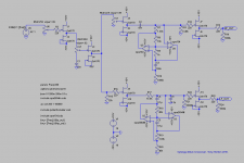
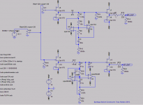
I've attached here the revised schematic (updated from the one in the blog). A zip with everything in it you need to get the sim up and running in LTSpice and a couple of distortion specta plots from the sim at 1Khz.
The BSC bit is completely optional depending on whether you need it or not (or would like to do it differently). Removing the bsc allows you to remove one additional B1 Buffer reducing from six to five (per channel). This will also improve the THD results for the high pass section, as I think the extra 3db (as configured) cut on the primary results in higher overall THD (though I’m not exactly sure why). Certainly the THD at the point before the HP section seems unchanged with or without the BSC circuit in place.
Also I have only put a pot in the high pass section for adjusting the levels as I my woofers are only around 89db whereas my MTM's are around 91db or higher efficiency. You can put another pot in the low pass or remove the one from the high pass without issue. I put a pot on the front, as this unit is also going to be my "pre-amp". I will be adding input switching, but it is not relevant for this thread.
It seems that both the High and Low pass sections have an insertion loss of about 3db. This I guess is not too bad.
Distortion figures from Fourier analysis in spice are below: and yes that did take 1 hour for the transient analysis!
Fourier components of V(lp_out)
DC component:1.43126e-005
Harmonic Frequency Fourier Normalized Phase Normalized
Number [Hz] Component Component [degree] Phase [deg]
1 2.000e+02 4.724e-01 1.000e+00 -93.25° 0.00°
2 4.000e+02 1.502e-06 3.180e-06 -71.88° 21.37°
3 6.000e+02 3.675e-09 7.780e-09 -105.91° -12.66°
4 8.000e+02 7.606e-11 1.610e-10 -128.58° -35.33°
5 1.000e+03 5.580e-11 1.181e-10 -132.80° -39.55°
6 1.200e+03 1.077e-10 2.280e-10 -75.90° 17.35°
7 1.400e+03 4.450e-11 9.421e-11 -123.32° -30.07°
8 1.600e+03 3.524e-11 7.462e-11 -92.67° 0.58°
9 1.800e+03 8.054e-11 1.705e-10 -102.07° -8.82°
Total Harmonic Distortion: 0.000318%
Fourier components of V(hp_out)
DC component:-1.08914e-005
Harmonic Frequency Fourier Normalized Phase Normalized
Number [Hz] Component Component [degree] Phase [deg]
1 2.000e+02 4.637e-01 1.000e+00 85.62° 0.00°
2 4.000e+02 3.696e-06 7.970e-06 144.84° 59.22°
3 6.000e+02 3.634e-08 7.838e-08 65.57° -20.06°
4 8.000e+02 5.656e-10 1.220e-09 2.21° -83.41°
5 1.000e+03 6.709e-11 1.447e-10 -61.22° -146.84°
6 1.200e+03 5.023e-11 1.083e-10 -50.12° -135.75°
7 1.400e+03 4.380e-11 9.446e-11 148.42° 62.80°
8 1.600e+03 2.629e-11 5.670e-11 -1.80° -87.42°
9 1.800e+03 1.402e-10 3.023e-10 139.72° 54.10°
Total Harmonic Distortion: 0.000797%
Date: Sun Apr 11 15:08:15 2010
Total elapsed time: 3607.593 seconds.
As can be seen the High pass exhibits more distortion than the low pass (which is kinda ironic since I would prefer it to be the other way around) but at this point I've just about given up trying to improve that, as I think it will be completely acceptable as is.
So here it is. It might be a few weeks before there is a (hopefully) working prototype, and I have no plans on making a pcb, as I’m going to make it on verro board). I would recommend reading the blog entry (even though it is longer than this post!! for more detail if you are interested in trying to make one of these for yourself.
Cheers,
Tony.
So here I present the Synergy "Active" Crossover. Please note I have only simmed it at this stage (and when I started I knew nothing about active filter design) so there is no guarantee it will work.
The design goal was to have an active crossover that for all intents and purposes is transparent. That is it does nothing other than split the frequencies at the desired crossover point.... Perhaps a bit of a lofty (and unrealisable goal) but this is the result thus far.
For a rather verbose description of how I arrived at this point please see my blog entry. There is also some initial discussion in the comments with a worked out example of how to arrive at the values for the FDNR (frequency dependent Negative Resistor).
The first lot of parts will be hopefully arriving on Tuesday. I still need to finalise the BOM for the rest of the parts and get the order in for them, but that will be a local order so should only have a few days lead time with luck.
I've attached here the revised schematic (updated from the one in the blog). A zip with everything in it you need to get the sim up and running in LTSpice and a couple of distortion specta plots from the sim at 1Khz.
The BSC bit is completely optional depending on whether you need it or not (or would like to do it differently). Removing the bsc allows you to remove one additional B1 Buffer reducing from six to five (per channel). This will also improve the THD results for the high pass section, as I think the extra 3db (as configured) cut on the primary results in higher overall THD (though I’m not exactly sure why). Certainly the THD at the point before the HP section seems unchanged with or without the BSC circuit in place.
Also I have only put a pot in the high pass section for adjusting the levels as I my woofers are only around 89db whereas my MTM's are around 91db or higher efficiency. You can put another pot in the low pass or remove the one from the high pass without issue. I put a pot on the front, as this unit is also going to be my "pre-amp". I will be adding input switching, but it is not relevant for this thread.
It seems that both the High and Low pass sections have an insertion loss of about 3db. This I guess is not too bad.
Distortion figures from Fourier analysis in spice are below: and yes that did take 1 hour for the transient analysis!
Fourier components of V(lp_out)
DC component:1.43126e-005
Harmonic Frequency Fourier Normalized Phase Normalized
Number [Hz] Component Component [degree] Phase [deg]
1 2.000e+02 4.724e-01 1.000e+00 -93.25° 0.00°
2 4.000e+02 1.502e-06 3.180e-06 -71.88° 21.37°
3 6.000e+02 3.675e-09 7.780e-09 -105.91° -12.66°
4 8.000e+02 7.606e-11 1.610e-10 -128.58° -35.33°
5 1.000e+03 5.580e-11 1.181e-10 -132.80° -39.55°
6 1.200e+03 1.077e-10 2.280e-10 -75.90° 17.35°
7 1.400e+03 4.450e-11 9.421e-11 -123.32° -30.07°
8 1.600e+03 3.524e-11 7.462e-11 -92.67° 0.58°
9 1.800e+03 8.054e-11 1.705e-10 -102.07° -8.82°
Total Harmonic Distortion: 0.000318%
Fourier components of V(hp_out)
DC component:-1.08914e-005
Harmonic Frequency Fourier Normalized Phase Normalized
Number [Hz] Component Component [degree] Phase [deg]
1 2.000e+02 4.637e-01 1.000e+00 85.62° 0.00°
2 4.000e+02 3.696e-06 7.970e-06 144.84° 59.22°
3 6.000e+02 3.634e-08 7.838e-08 65.57° -20.06°
4 8.000e+02 5.656e-10 1.220e-09 2.21° -83.41°
5 1.000e+03 6.709e-11 1.447e-10 -61.22° -146.84°
6 1.200e+03 5.023e-11 1.083e-10 -50.12° -135.75°
7 1.400e+03 4.380e-11 9.446e-11 148.42° 62.80°
8 1.600e+03 2.629e-11 5.670e-11 -1.80° -87.42°
9 1.800e+03 1.402e-10 3.023e-10 139.72° 54.10°
Total Harmonic Distortion: 0.000797%
Date: Sun Apr 11 15:08:15 2010
Total elapsed time: 3607.593 seconds.
As can be seen the High pass exhibits more distortion than the low pass (which is kinda ironic since I would prefer it to be the other way around) but at this point I've just about given up trying to improve that, as I think it will be completely acceptable as is.
So here it is. It might be a few weeks before there is a (hopefully) working prototype, and I have no plans on making a pcb, as I’m going to make it on verro board). I would recommend reading the blog entry (even though it is longer than this post!! for more detail if you are interested in trying to make one of these for yourself.
Cheers,
Tony.
Attachments
Last edited:
I see there have been a few downloads of the sim file. If anyone is having trouble with it coming up with the singular matrix message when running a transient response, then go to the menu simulate/control panel, click on the spice tab and change the solver to alternate. This should fix the problem (I'd forgotten I had to do that). I wasn't able to work out what was causing the failure , but I don't think it is actually a problem with the circuit.
Tony.
Tony.
I find your simulation of the open loop buffer rather optimistic. I build that circuit several times but i used LSK389C and it had much higher distortion then your simulation shows measured on an Audio Precission at Jan Didden.
Do not take me wrong, it´s a great sounding circuit and it adds only low order harmonics,
mostly second. To overcome that i designed a buffer that is a modern interpretation of the JLH buffer. It has higher speed ( -3dB @14,5MHz) and much lower distortion.
It peaks slightly over 10Mhz so some soft RF filtering at the input improves squarewave response. I measured a -3dB point of 6Mhz in the LSK389C buffer but only when it´s driven by a low impedance source. No overshot here and of cause the bandwidth is much higher then required for fidelity in the audiorange. A friend of mine uses that buffer ( the LSK389C ) with his Audio Aero CD player and claims that his system sounds much better now. Strickly speaking this buffer is not transparent but adds subjectively extremely pleasing distortion although on such a low level that it does not sound distorted at all. Silly, isn´t it ?
Anyway, i like your circuit very much and i am eager to now how it performs when you actually build it.
Attachments
Thanks Joachim,
Yes you are right the distortion figures are very optimistic, but such is the nature of a sim") The B1 buffer used (Nelson Pass' design, modified by Salas for dual rail supply, Thanks Nelson and Salas!!) when Nelson tested typically has 0.0007% distortion. So one would expect that the distortion results with a few of them cascaded and additional filter circuit inserted should definitely be higher!! I should have mentioned that
The B1 buffer used (Nelson Pass' design, modified by Salas for dual rail supply, Thanks Nelson and Salas!!) when Nelson tested typically has 0.0007% distortion. So one would expect that the distortion results with a few of them cascaded and additional filter circuit inserted should definitely be higher!! I should have mentioned that
I narrowed down (through elimination) the higher distortion in the high pass circuit to the series capacitor... increasing the value of this cap reduces the distortion, with the trade off that the load resistor has to go down... I'm not sure how low I can get away with for the load resistor, but intuition tells me not much lower than the 8.5K that Is in the sim at the moment. Interestingly the distortion in the sim is higher if I remove the opamp in the high pass and make it 1st order (ie only the cap), ie the introduction of the GIC circuit actually lowers the distortion, I don't actually understand what is happening here with this cap and the distortion.
I was comparing the distortion to a sallen key implementation last night (again in a sim)... at 200Hz the sallen key has slightly higher distortion (3rd harmonic is quite a bit higher) but at 400Hz the sallen key is quite a bit lower... The GIC simulated coil seems to not have a linear distortion, ie the amount of distortion varies with freq. It seems worst at 2X or 1/2 the corner frequency and best at about 1.5 X the corner freq... Whether or not this will be a problem waits to be seen. (actually I should do a test with just the cap before drawing this conclusion, as it might not be the GIC at all).
I'm still finalizing the parts, have received most of them (but not everything for the powersupply).
So hopefully by next Sat I will be able to start building something, time permitting
Of course any buffer that you like could be used. I just chose Nelson's because I liked the philosophy of it and it's simplicity, and once I've built it I will finally be able to say that I've built something from Pass Labs
Jameshillj also asked about using another buffer The JC Buffer, I was going to sim it too but haven't got around to it. At the moment I have the jfets I need to build the B1 so that is what I'll use
Tony.
Yes you are right the distortion figures are very optimistic, but such is the nature of a sim
The B1 buffer used (Nelson Pass' design, modified by Salas for dual rail supply, Thanks Nelson and Salas!!) when Nelson tested typically has 0.0007% distortion. So one would expect that the distortion results with a few of them cascaded and additional filter circuit inserted should definitely be higher!! I should have mentioned that I narrowed down (through elimination) the higher distortion in the high pass circuit to the series capacitor... increasing the value of this cap reduces the distortion, with the trade off that the load resistor has to go down... I'm not sure how low I can get away with for the load resistor, but intuition tells me not much lower than the 8.5K that Is in the sim at the moment. Interestingly the distortion in the sim is higher if I remove the opamp in the high pass and make it 1st order (ie only the cap), ie the introduction of the GIC circuit actually lowers the distortion, I don't actually understand what is happening here with this cap and the distortion.
I was comparing the distortion to a sallen key implementation last night (again in a sim)... at 200Hz the sallen key has slightly higher distortion (3rd harmonic is quite a bit higher) but at 400Hz the sallen key is quite a bit lower... The GIC simulated coil seems to not have a linear distortion, ie the amount of distortion varies with freq. It seems worst at 2X or 1/2 the corner frequency and best at about 1.5 X the corner freq... Whether or not this will be a problem waits to be seen. (actually I should do a test with just the cap before drawing this conclusion, as it might not be the GIC at all).
I'm still finalizing the parts, have received most of them (but not everything for the powersupply).
So hopefully by next Sat I will be able to start building something, time permitting
Of course any buffer that you like could be used. I just chose Nelson's because I liked the philosophy of it and it's simplicity, and once I've built it I will finally be able to say that I've built something from Pass Labs
Jameshillj also asked about using another buffer The JC Buffer, I was going to sim it too but haven't got around to it. At the moment I have the jfets I need to build the B1 so that is what I'll use
Tony.
The Pass buffer has lower distortion as the Salas because it has biasing at the expense of two coupling caps.
The JC buffer should have lower 2nd harmonic because of parallel symmetric design but can not compete with mine on terms of distortion.
i modified a lot of CD players in the 80th ( mostly Phillips) with GIGs. I got that idea from Walt Jung so you may find some information on his website. As far as i remember my customers where very happy with the result. I think Swoboda dose something like that but i have not talked to him for a long time. I a nutshell i think they sound good because they are not in the direct signal path. Jürgen Ultee of DAAS fame knows also a lot about simulated inductors. He uses circuits like that in the PSU of his Inductive Phonostage for Van den Hul. Very good to see work on that interesting circuit.
Hi Joachim,
I actually found out about the GIC circuits from the book Walt Jung wrote on opamps, which Analog Devices has for download The shunt aspect of the circuit definitely appealed to me, as did the fact that I couldn't find anyone else who had made an active crossover using them (at least not publicised it).
I've been measuring my speakers today. They don't sound like they have any distortion problems, but apparently they distort about 2% at around 800Hz (and about 0.6% at other frequencies, unless it is my measurements)! So I think even if I have 0.01% out of this circuit I shouldn't worry too much
I noted the similarity of your circuit to the JC buffer, but with extra transistors. If I have time I'll sim it too out of interest, but I really must work on finalising what parts I need to order, otherwise this circuit will never get built!!
Tony.
I actually found out about the GIC circuits from the book Walt Jung wrote on opamps, which Analog Devices has for download
The shunt aspect of the circuit definitely appealed to me, as did the fact that I couldn't find anyone else who had made an active crossover using them (at least not publicised it). I've been measuring my speakers today. They don't sound like they have any distortion problems, but apparently they distort about 2% at around 800Hz (and about 0.6% at other frequencies, unless it is my measurements)! So I think even if I have 0.01% out of this circuit I shouldn't worry too much
I noted the similarity of your circuit to the JC buffer, but with extra transistors. If I have time I'll sim it too out of interest, but I really must work on finalising what parts I need to order, otherwise this circuit will never get built!!
Tony.
ok well it has been nearly two years, but I have finally bread boarded the high pass section of the circuit Low pass will hopefully get done some time this week!
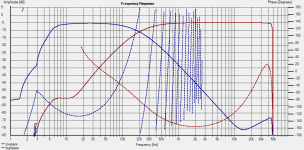
The only reliable measurement I've been able to do so far (my sound card is acting up as it does sometimes under win7 64bit) has been the transfer function of the circuit.
I didn't have the exact resistors I needed so I have built with slightly off values, but even then it is very close to the 2nd order L/R slope that the resistor values were calculated for.
I've gone with the Salas DC B1 with a bit of a twist. Because I am not using a shunt reg, I've used 1000uF caps per rail with the 1 ohm resistor decoupling from the PS. There will be separate ones for each channel which should help decouple from the PS a little I hope. I've also eliminated the 220 ohm resistors on the input to the second B1. input resistor was reduced from 22k to 12k as well. This resistor seems to affect the distortion figures in the sim quite a bit, and 12k was about the sweet spot.
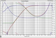
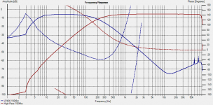
The attachment shows Blue curve sound card loopback measurement, orange curve, 2nd order L/R target at 200Hz generated in PCD. Red curve is the actual measurement of the circuit.
I tried to do some distortion measurements but was getting 0.33% thd on loopback on my sound card, (normally it is around 0.003%) so I abandoned that for now.
Tony.
Low pass will hopefully get done some time this week! The only reliable measurement I've been able to do so far (my sound card is acting up as it does sometimes under win7 64bit) has been the transfer function of the circuit.
I didn't have the exact resistors I needed so I have built with slightly off values, but even then it is very close to the 2nd order L/R slope that the resistor values were calculated for.
I've gone with the Salas DC B1 with a bit of a twist. Because I am not using a shunt reg, I've used 1000uF caps per rail with the 1 ohm resistor decoupling from the PS. There will be separate ones for each channel which should help decouple from the PS a little I hope. I've also eliminated the 220 ohm resistors on the input to the second B1. input resistor was reduced from 22k to 12k as well. This resistor seems to affect the distortion figures in the sim quite a bit, and 12k was about the sweet spot.
The attachment shows Blue curve sound card loopback measurement, orange curve, 2nd order L/R target at 200Hz generated in PCD. Red curve is the actual measurement of the circuit.
I tried to do some distortion measurements but was getting 0.33% thd on loopback on my sound card, (normally it is around 0.003%) so I abandoned that for now.
Tony.
Attachments
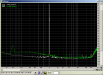
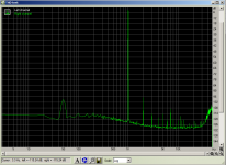
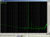
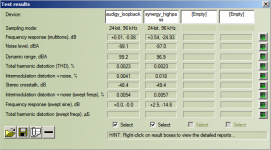
I decided to try my luck on an rmaa measurement again tonight and got a better result. RMAA reported 0.0023 for the loop back measurement and 0.0023 with the synergy inserted. This was running in mono mode as I have only built one channel.
Attached are in order. THD spectrum for the sound card, THD spectrum for the synergy, and overlay of the two.
The 50Hz is the usual hump I get due to ground loops when measuring with this pc.
Overall considering this is just thrown together on breadboard at the moment I don't think it is too bad a result
I think RMAA got a bit confused by the roll-off of the crossover and bumped the level up 3.5db on the second measurement. The IMD was not great, but I suspect that was also due to the fact that one of the tones was 50Hz which is well under the 200Hz crossover frequency, the swept tones IMD was very similar to the sound card but a bit more ragged.
edit: looking at the THD plots it is interesting that some of the synergy results are lower than the loop back for the sound card, not sure how that could be. 7th harmonic is the only one that looks much worse (4th is non existent on the sound card loop back measurement).
Tony.
Attachments
Last edited:
Hi Al,
The OPA2134's have lower distortion and work fine in the high pass, but do not behave as well as the OPA2604's in the low pass circuit (at least in the sim). There is a problem with some sort of resonance in the low pass circuit which I've finally been able to reduce the effects of (it was originally at around 20Khz but I've now pushed it out to about 40Khz which is a long way above the 200Hz crossover freq), I haven't retried the sim with the OPA2134's after the mod. The effects of this "resonance" varied quite dramatically with different opamp models in the sim.
Once I've breadboarded the low pass, I will try it with both the opa2134 and opa2604's and see whether there are any measurable differences. I'll also try out a TL074 as I have one in my junk box.
Tony.
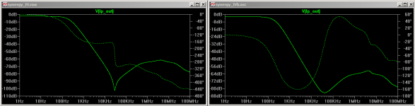
Below is an attachment which shows the problem with the lowpass circuit. left is the original, right is after changing the two 40K resistors to 33k (below 40K previously resulted in oscillation in the sim) and a 220pF cap across the top 33K resistor.
This smooths out the dip and also gets rid of the nastiest part of the phase change. I'd ideally like the phase to remain flat but I think this is much more benign that the first one. I suspect the original oscillations were phase margin related.
Unfortunately I don't understand what causes the deviation from the filter slope and phase change so my "fix" for it is from trial and error. If I actually understood what was going on I might be able to fix it properly. My hope is that because it is so far down that it will be basically not a problem.
I've also attached the latest version of the simulation schematic. Real world implemtation has 100nf caps on the opamp power pins and 1000uF caps on the rails decoupled from the ps with a 1 ohm resistor.
Tony.
Attachments
Joachim Gerhard said:The Pass buffer has lower distortion as the Salas because it has biasing at the expense of two coupling caps.
How does the different bias voltage affect distortion? I don't see why it would make any difference.
I'm not too familiar with the Salas circuit, apart from that it uses a dual rail supply to eliminate coupling caps. Aren't they both biased at Idss?
I think what Joachim is saying is that the distortion on the original is higher because of the need for coupling capacitors (ie it is the coupling capacitors that are adding to the distortion). The split rail makes it possible to eliminate the coupling capacitors because the input is not at 1/2 the potential of the power supply, it is at zero volts
BTW I measured the dc offset (I forgot to mention) and it was 0.8mV I can't remember if that was positive or negative. I didn't match the jfets, but I did use jfets from a bunch that I had sorted into 7-7.5 mA idss so they would have been close.
Tony.
BTW I measured the dc offset (I forgot to mention) and it was 0.8mV I can't remember if that was positive or negative. I didn't match the jfets, but I did use jfets from a bunch that I had sorted into 7-7.5 mA idss so they would have been close.
Tony.
There is a problem with some sort of resonance in the low pass circuit which I've finally been able to reduce the effects of (it was originally at around 20Khz but I've now pushed it out to about 40Khz which is a long way above the 200Hz crossover freq), I haven't retried the sim with the OPA2134's after the mod.
That's why I just build rather than simulate, I find it so much easier to troubleshoot a real world "thing". For crossover type circuits, I just wire in a DIL socket for components that are likely to change, then you can just plug in various values quickly.
Hi Al, I've done half the low pass on the breadboard tonight Too tired to finish it, and I know from past experience it is best to stop when I feel tired I will be very interested to see whether the resonance is a figment of the sims imagination or a real world occurrence.
I would be exceptionally happy if it is fictitious, but the irony would not be lost on me, as I spent a lot of time trying to get rid of it
If this circuit is successful I think I will be more motivated to build stuff more quickly, as that will be two successful "designs" under my belt.
I decided to have a crack at learning spice because I lacked the confidence to build something I had dreamt up myself (actually I think the first thing I simulated was SY's acheron which was the inspiration for this circuit!!)
I was scared my circuit would blow up, and wanted some reassurance from the sim that it had a chance of working. Simulation seemed to be the easiest (and quickest) way to test out some ideas to see if they had merit or not, unfortunately my obsessive nature meant that it became an exercise in tweaking that went on for a long time and eventually I was burned out and left it for a long time. I actually bought most of the parts for this back in April 2010.....
I didn't have a bread board when I started to sim (I'm so glad I bought one). My next biggest problem once I have verified it works on the breadboard will be working out the layout for the "final" board. Oh well I'll get there eventually!!
Tony.
Too tired to finish it, and I know from past experience it is best to stop when I feel tired I will be very interested to see whether the resonance is a figment of the sims imagination or a real world occurrence. I would be exceptionally happy if it is fictitious, but the irony would not be lost on me, as I spent a lot of time trying to get rid of it
If this circuit is successful I think I will be more motivated to build stuff more quickly, as that will be two successful "designs" under my belt.
I decided to have a crack at learning spice because I lacked the confidence to build something I had dreamt up myself (actually I think the first thing I simulated was SY's acheron which was the inspiration for this circuit!!)
I was scared my circuit would blow up, and wanted some reassurance from the sim that it had a chance of working. Simulation seemed to be the easiest (and quickest) way to test out some ideas to see if they had merit or not, unfortunately my obsessive nature meant that it became an exercise in tweaking that went on for a long time and eventually I was burned out and left it for a long time. I actually bought most of the parts for this back in April 2010.....
I didn't have a bread board when I started to sim (I'm so glad I bought one). My next biggest problem once I have verified it works on the breadboard will be working out the layout for the "final" board. Oh well I'll get there eventually!!
Tony.
I decided to have a crack at learning spice because I lacked the confidence to build something I had dreamt up myself (actually I think the first thing I simulated was SY's acheron which was the inspiration for this circuit!!)
Found my math mistakes while you were at it?
I'll fix them one of these days... since going digital, my motivation for updating that article has dropped to near-zero.So the lowpass part of the circuit has been realised this evening. I have done the original circuit without the 220pf cap and the 40K resistors just to see how it went compared to the sim. Well it actually peters out at about 15K rather than 20K and the phase (according to holm impulse) is all over the place!! but I'm not sure that it is showing what I think it is...
I'll have to get some 220pf caps so I can try that mod and see what the effect is. I did try to get a 192Khz measurement with my onboard sound, but it was way too noisy and basically useless.
anyway here it is.
Tony.
I'll have to get some 220pf caps so I can try that mod and see what the effect is. I did try to get a 192Khz measurement with my onboard sound, but it was way too noisy and basically useless.
anyway here it is.
Tony.
Attachments
ok so I worked out what was going on with the phase. The impusle was negative and detect time zero was set to highest positive peak
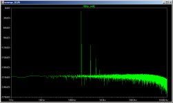
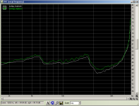
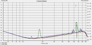
I've done some measurements tonight at 192Khz with the onboard sound. There appears to be some resonance at around 58Khz and 75Khz.
In the sim I had to use 40K resistors in the lp circuit to get stability anything less than that and I had problems, so I decided to try with 33K and 22K.
The graph below has had all curves smoothed 1/48th octave as they were a tad hairy. Blue is with 40K resistors, red with 33K resistors and orange with 22K resistors.
Its obvious that 22K resistors are an issue I think I will stick with the 40K's and hope that the little peaks at 58 and 75k don't give my amp any problems. since they are at around -55db and it will be driving a 10" at 200Hz crossover frequency hopefully not
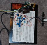
I've also included a picture of the current implementation which may have a lot to do with the spikes. There has been zero consideration given to grounding, and component leads have not been trimmed. basically a rats nest of poorly laid out components.
I may do a listening test to the one channel tomorrow if I get a chance.
Tony.
I've done some measurements tonight at 192Khz with the onboard sound. There appears to be some resonance at around 58Khz and 75Khz.
In the sim I had to use 40K resistors in the lp circuit to get stability anything less than that and I had problems, so I decided to try with 33K and 22K.
The graph below has had all curves smoothed 1/48th octave as they were a tad hairy. Blue is with 40K resistors, red with 33K resistors and orange with 22K resistors.
Its obvious that 22K resistors are an issue
I think I will stick with the 40K's and hope that the little peaks at 58 and 75k don't give my amp any problems. since they are at around -55db and it will be driving a 10" at 200Hz crossover frequency hopefully not I've also included a picture of the current implementation which may have a lot to do with the spikes. There has been zero consideration given to grounding, and component leads have not been trimmed. basically a rats nest of poorly laid out components.
I may do a listening test to the one channel tomorrow if I get a chance.
Tony.
Attachments
Ah Tony,
Good to see you've got back to this project and that the 'gyrators' are showing promise.
If you are still using the cct as per post #11, could you try a couple of things - first, can you get rid of that extra vol pot in the input to the high pass filter and replace it with a nominal gate stopper (ie 22R) and same for that 12k resistor on low pass input?
For vol control, could you just add a pot on output of low pass followed with another buffer?
Also, could you try (in the sim) replacing the main input vol pot of 25kR with a rather low one of 7kR as this is about the load of a Lightspeed vol control, I think.
my Offer of a pcb 'pre-design' is still there - trying to learn the new pcb program "Sprint" to replace my prehistoric Protel (but still works just fine!)
Playing with Stu's 'Acheron' but with Aikido buffers instead of the 'Hereticals'- looks promising ...
- Status
- This old topic is closed. If you want to reopen this topic, contact a moderator using the "Report Post" button.
- Home
- Source & Line
- Analog Line Level
- The Synergy "Active" Crossover