Hi James, yes it was the phase that was bugging me too. What I found worked well (in my sim) was 2nd order on the HP and 3rd order on the LP. This gave very good phase tracking and I was able to tweak it to get a good 4th order acoustic slope.
This is an area I never see addressed with analog active crossovers. Everything I've seen is basically a text book 2nd order or 4th order LR.
That in my books is no different to doing a text book 2nd or 4th order passive crossover (with the exception that you don't get the additional problems that varying speaker impedance causes).
To get the best out of any active crossover I believe that you need to design the filter to give you the target acoustic slope you want. This is something that I suspect is much easier with DSP's and probably why they are popular now.
On the changes when you don't have any passives in place, it could be due to inherent DCR in the passive components. An increase in resistance between the amp and the speaker will change the alignment of the box. Depending on how much resistance there is this can be quite a difference. You could try installing a low value (high wattage) resistor say 0.3ohms in series with the bass drivers when running direct active and see what difference that makes.
Tony.
I've been meaning to have a look at how the extra programs that are added to the jRivers operating system work and particularly if it's possible to add in a specific 'anti-phase' plot for phase correction - I think it should be possible but not sure if the jRivers design includes the facility, or even if it doesn't produce other problems
There's a few pro-audio programs that do include this specific feature but, unfortunately, most don't seem to sound 'good' on audio playback - this is one of my disappointments with that Berhinger box, even with the full house upgrades, despite it's whole truckload of facilities.
Rod Elliot has a few words to say about phase response with electronic Xovers and then there's the Linwitz papers plus quite a bit about this in the Rane site - nearly all of them require much more IC packages in the signal line but maybe with such good results with the dcB1 stages, it may be quite possible to add some phase correction filters onto the electronic Xover filters without degrading the signal too much, if at all - dunno.
About filter slopes, I'm entirely in agreement, particularly when you add the effects/design of the chambers to the mix - my mid sphere is just under 18" dia with a 'tail' (tapered resistance damping) and this an additional component in total Xover filter.
Yes, done the Qts adjustment with the series resistor 'thing' but generally on the FR driver, not the bass unit - have 2 amps now so this is now done for fine tuning rather than trimming for variations in driver efficiency - also, another point to experiments with different types of resistors to adjust the sound - got a few different types of resistance wires now to play with ....
Amp output stage <-> driver impedance loading has disappeared from hifi discussions these days - relegated to 'snake oil' stuff mostly - stupid really as there's enormous benefits to be obtained
Trying to 'pretty-up' my Shroeder diffusers - not so easy, and the bloody dustcollector Skylines are beyond help - good thing they work so well!
Hi James, from what I have done with passive crossovers you can get good phase matching with combinations of odd and even electrical orders. Additionally you can get the same overall slope with electrical 2nd or 3rd order filters just by playing with the values. This means if I am not wrong that I can develop a passive filter (in simulation) and realise it with the synergy to get phase matching right.
This requires one additional resistor or one additional capacitor to change the low pass or high pass from a 2nd order electrical to a 3rd order electrical filter.
Provided large phase changes are not necessary additional circuitry such as all pass filters should not be necessary.
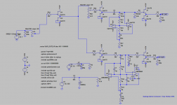
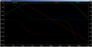
I've zipped up my latest circuit iteration with values that will give a textbook 2nd order LR at 140 Hz. Also attached are screen grabs showing the circuit and simulated output.
Note I have not yet tried an LME49860 It would not do well in the breadboard. The opa2134 is the only one I have physically tried.
I realized that the blog page doesn't have any info on how to work out the high pass filter values. I will do something about that.
Both the high pass and the low pass use different values that calculated to get the best result. I put in the textbook coil and cap and then tweak the values in the circuit to get a good fit to that. Research I've seen on inductors and fdnr's does show that they are out in value compared to what they theoretically should be, luckily spice takes some of the guesswork out") When I did the breadboard, I'm pretty sure I compared the measured response to a theoretical curve and it was a good match.
When I did the breadboard, I'm pretty sure I compared the measured response to a theoretical curve and it was a good match.
The attached spice zip file should be self contained, so you should be able to run from the directory without adding anything into spice. You may have to change the solver to gear, the lme49860 seems to take for ever to converge with the normal solver. Actually I just checked and I have been using the Modified Trap with alternate solver.
Tony.
This requires one additional resistor or one additional capacitor to change the low pass or high pass from a 2nd order electrical to a 3rd order electrical filter.
Provided large phase changes are not necessary additional circuitry such as all pass filters should not be necessary.
I've zipped up my latest circuit iteration with values that will give a textbook 2nd order LR at 140 Hz. Also attached are screen grabs showing the circuit and simulated output.
Note I have not yet tried an LME49860 It would not do well in the breadboard. The opa2134 is the only one I have physically tried.
I realized that the blog page doesn't have any info on how to work out the high pass filter values. I will do something about that.
Both the high pass and the low pass use different values that calculated to get the best result. I put in the textbook coil and cap and then tweak the values in the circuit to get a good fit to that. Research I've seen on inductors and fdnr's does show that they are out in value compared to what they theoretically should be, luckily spice takes some of the guesswork out
When I did the breadboard, I'm pretty sure I compared the measured response to a theoretical curve and it was a good match. The attached spice zip file should be self contained, so you should be able to run from the directory without adding anything into spice. You may have to change the solver to gear, the lme49860 seems to take for ever to converge with the normal solver. Actually I just checked and I have been using the Modified Trap with alternate solver.
Tony.
Attachments
Last edited:
I have to admit that I haven't as yet managed to get the hang of that SIM stuff at all
However, what I can do is have a crack at outlining the pcbs for your edification (how about that one!) - I'll knock up a pre-design with the Express pcb designer as it's a fairly easy single/2 layer program and can get all fancy later as it comes together - my humble contribution to the project.
Curiously, a few days ago, I attended an AES presentation by Bohdan Raczynski (Bodzio Software) and it was all about his Ultimate equalization Software, a DSP package designed to sort out the very phase control Xover problems/system that you mentioned above - very interesting - he developed the "Sound Easy" program - good gear
Hi James, If you would like to do a board go for it. If you can do something that is diy-able (ie that people can etch at home) that would be good. The layout I posted above, is I think, not really something that someone could etch them self (unless they are very good at it). It is pretty much a board-house job I think. Maybe you want to do one with Salen key Low pass? I do hope that the FDNR is going to be a success though.
I think my layout is good enough for me to get some prototypes done, I just have to get my head around the various gerber files I need to create for the board house to get some made (this is my first board design).
I've used some SMD components as well (caps) which may some turn people off.
Tony.
I think my layout is good enough for me to get some prototypes done, I just have to get my head around the various gerber files I need to create for the board house to get some made (this is my first board design).
I've used some SMD components as well (caps) which may some turn people off.
Tony.
Okay, will look to see if a maybe double sided board will be okay - would do a single sided one but the power supply lines and ground returns make it pretty poor quality design - will see about a SK option too
I have some really old stock of some Rifa Styrene caps (pfe216, I think) and they're very good indeed but quite large size - this might create unacceptable wasted spaces if you're looking for SMD consolidation - we'll see how it shapes up.
Unfortunately, I'm a bit slow with this stuff, but ....
I have some really old stock of some Rifa Styrene caps (pfe216, I think) and they're very good indeed but quite large size - this might create unacceptable wasted spaces if you're looking for SMD consolidation - we'll see how it shapes up.
Unfortunately, I'm a bit slow with this stuff, but ....
2SK2145 as replacement part for a pair of 2sk170 in sallen key?
Hello,
2SK2145 are widely available.
Do you think a 2SK2145 (dual jfet n channel common source) could be sucessfully used in a sallen key topology?
I don't know much about the manufacturing process of transistors, but does it mean that the 2 jfet provided in a 2SK2145 is a matched pair?
Hello,
2SK2145 are widely available.
Do you think a 2SK2145 (dual jfet n channel common source) could be sucessfully used in a sallen key topology?
I don't know much about the manufacturing process of transistors, but does it mean that the 2 jfet provided in a 2SK2145 is a matched pair?
Hi nicotin78, I'm not able to give you an answer to that, as it is outside of my knowledge area, but you may have more luck asking in the B1 active crossover thread http://www.diyaudio.com/forums/pass-labs/156094-b1-active-crossover.html There is another more recent version I've seen as well but I can't remember where it is.
Tony.
Tony.
very interesting thread
Hi,
Intriguing thread, which i will be following with interest.
I have myself been in the process of designing an analogue active filter, except i am using sallen key stages to achieve a roughly 4th order alignment (well 4th and 6th approximated, in acoustic response) which gives me a typical 4th order phase alignment of near 0deg at crossover (0 deg plus one cycle).
Its nice to see another fellow targeting acoustic output using arbitrary curves, rather than textbook filters.
Do you have a thread mondogenerator? I'd be interested to know how you are working out your components for Sallen Key for arbitrary curves. It is an area that I think can make the difference between an ok and a really great implementation.
The acoustic slope (and the phase matching) is what really matters and I think is largely overlooked with the typical active crossovers being used by diyers (except in the digital realm).
Tony.
The acoustic slope (and the phase matching) is what really matters and I think is largely overlooked with the typical active crossovers being used by diyers (except in the digital realm).
Tony.
Hi Wintermute,
Sure I dont mind sharing
My passive to active conversion project is based on my current system (2 way Visaton TQWT)
Its a little case specific since I used Boxsim to simulate the passive implementation, and Im confident in the program accuracy as all sounded as flat as predicted in the sim.
Im technically a beginner, but I try hard and whilst im not nearly as knowledgable as even the majority of people here, i have felt my way through the conversion.
Anyway, Boxsim also has an active section, where you can use up to 5 orders of filtering and play with Q and Fc, apply, and see the simmed response in the acoustic response. Although Boxsim can be used for other driver manufacturers by inputting .frd and .zma, its a little troublesome and to date I have only bothered to do this with a couple of drivers (fountek Neo3.5h, and a couple of small TBs)
I have a couple of threads which document fragments of this project (and also document my inexperience in a lot of the techy side of these things)
They are:
http://www.diyaudio.com/forums/analog-line-level/241649-filter-q-question-7.html
(first few posts of mine are a bit dumb, but with DF96 and AndrewT help I get there eventually)
and:
http://www.diyaudio.com/forums/mult...ve-conversion-can-someone-check-my-logic.html
(post#8)
Also I was lazy with the maths and used a splendid calculator I found in the link below. I plan to actually run through the maths proper (it depends if I end up using this as part of my degree assignment, and have to use some maths)
I am also in the process of using the electrical curves I simmed (in one of the linked threads) to approximate the TF for each stage, which I can then calc component values for, and then I can also sim the system TF in Matlab for comparison with the predicted response & measured responses. As yet I havent the time or talent to measure the real world acoustic output, but I am happy with verifying the electrical TF that Boxsim ouputs which corresponds to the simmed acoustic output.
http://sim.okawa-denshi.jp/en/Fkeisan.htm
Aside to mods: If I am not allowed to post this please delete the link. I dont wants no trouble....
Last edited:
Looks like you have the low pass sorted but that the high pass is giving you grief. The simmed vs actual is very different, so something's amiss.
I'm also very lazy when it comes to math, and I've been relying on online calculators to get starting points for the filters. I suspect you are actually ahead of me on filter theory!
BTW I see no problem with the link
Tony.
I'm also very lazy when it comes to math, and I've been relying on online calculators to get starting points for the filters. I suspect you are actually ahead of me on filter theory!
BTW I see no problem with the link
Tony.
Yes the highpass Q wasn't right, the two SK stage Fc were too far apart. Using the calculator i didn't get close enough to the desired turnover frequencies. With a little juggling of component values i go to within 30hz of the target frequencies. I haven't measured the curves again yet, but in theory the High pass should be much closer to the intended curve.
Hey I'm not more than a novice, and i had no idea what a fdnr was until reading this thread ��
Hey I'm not more than a novice, and i had no idea what a fdnr was until reading this thread ��
hehe I've relied heavily on experimentation to get where I am. I don't actually understand how the circuit works (my eyes start to glaze over when I try and understand the theory), but I've read enough and done enough simulations to get something that is doing (mostly) what I want it to
I get the impression from your comment that you can do the maths, but were being lazy. I on the otherhand looked at an already worked out example saw a relationship and then used that to derive the values I needed. All attempts at calculating from scratch (and I did try) failed
I'm one of those "knows enough to be dangerous" types. It's more tenacity than understanding that gets a result in the end. At the end though I have probably learnt at least something along the way
Tony.
Haha yeah lazy is correct. I have put the completion of the filters off until the university year is over and exams completed. I'm in my mid30s and i wish i had done the hard study in my teens! What i find unhelpful in uni learning is the techniques taught usually rely on the equal R or equal C Formulae, and reliance on textbook filter algebra. Of course it is done this way as it suits most filtering uses, and the math is considerably easier.
Speaking to AndrewT and DF96 was extremely useful in jogging my brain into thinking, particularly in respect to stage Qs for filter order.
The calculator was extremely useful in 'roughing out' the design quickly, until such time as i get time to work through the maths.
Speaking to AndrewT and DF96 was extremely useful in jogging my brain into thinking, particularly in respect to stage Qs for filter order.
The calculator was extremely useful in 'roughing out' the design quickly, until such time as i get time to work through the maths.
I did first year university science maths in 1985, differentiation and calculus I did manage to get my head around at the time and I passed, but it is so long ago (and I struggled with it then) that now I think it would require significant effort to "get up to speed"
I was reading an article in linear audio volume three this evening whilst waiting for the train on doing bi-quad filters and I very quickly skipped the theory section
I suspect sooner or later in this hobby I will have to bite the bullet and do the hard yards if I want to get past a certain level, but for now I'm content to stumble along
I stopped doing the science degree (Geology) and changed to computing science so have never needed the maths in my work life. There is a certain irony in that it would be really useful for one of my chosen hobbies!
Tony.
Last edited:
I might have finally reached the point where I don't want to change the layout every time I look at the board Latest version attached. I think this will be the one I get done. I've spent way too much time on this for a prototype but usually with me prototype is as far as it goes (ie the prototype ends up being used).
Hopefully the low pass works ok, I will have wasted a lot of time if it doesn't I think that this is a lot better than the earlier layouts I posted.
Tony.
Latest version attached. I think this will be the one I get done. I've spent way too much time on this for a prototype but usually with me prototype is as far as it goes (ie the prototype ends up being used). Hopefully the low pass works ok, I will have wasted a lot of time if it doesn't
I think that this is a lot better than the earlier layouts I posted. Tony.
Attachments
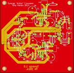
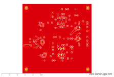
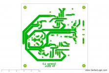
Hi James, Top layer is ground plane yes, but the main tracks are on the bottom side. I've attached separate pics of the top and bottom layers. I read after I started that ground planes were normally done on the bottom side with tracks on the top, but it felt more right to me to have the ground plane on the top.
I've tried to minimise the number of traces on the ground plane.
This is my first non-vero board layout so I'm learning as I go I did do a PS board in kikad for my power amps power supply but I haven't made that and it is not quite the same level of complexity
Tony.
I've tried to minimise the number of traces on the ground plane.
This is my first non-vero board layout so I'm learning as I go
I did do a PS board in kikad for my power amps power supply but I haven't made that and it is not quite the same level of complexity Tony.
Attachments
Last edited:
I think I'm a bit pre-historic in that I like clearly defined earth/0 volt tracking to control current return paths and aim for single sided pcbs for ease of making them - haven't any experience about this ground plane 0 volt system but for the purposes of filtering it sure seems a lot simpler - I wonder if I can do it with the simple Express program or if have to get serious with the Sprint Layout - hmmm ...
Really good that you have designed for non-SMD resistors , altho still applicable.
The big Rifa Styrene filter caps (pfe216) won't fit your allocated space altho maybe vertical mounting ....
As you say, you can redesign these things forever and never know if they sound any better/different until you actually build one
This looks pretty good so far - are you going to get more than one made when you order? (just a hint here!)
- Status
- This old topic is closed. If you want to reopen this topic, contact a moderator using the "Report Post" button.
- Home
- Source & Line
- Analog Line Level
- The Synergy "Active" Crossover