I like it. I'm a novice with PCB design (maybe 15 projects) and I'm also a dinosaur, i still struggle with double sided layouts, and prefer to keep to a single side, with topside links or components forming the links. Trying to do earths for HF and MF decoupling as AndrewT and others had suggested to me, was an enormous headache.
If i thought i could sell my efforts id probably draw up and double sided board and get a batch made, rather than plod along with a single sided effort and develop the PCB myself.")
If i thought i could sell my efforts id probably draw up and double sided board and get a batch made, rather than plod along with a single sided effort and develop the PCB myself.
There is a pair of boards earmarked for you once I get them and verify they are ok
Tony.
This looks pretty good so far - are you going to get more than one made when you order? (just a hint here!)
Yes the service I'm going to use does 10 boards for $19.95
as a prototyping service. No setup costs either!! Once I have them I'll send a pm to get your postal address I have a feeling I might already have it but not sure. Tony.
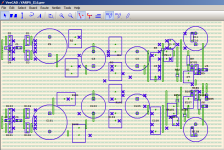
I decided to go with a ground plane after reading a number of layout guides. TI and I think analog Devices both had good ones. It also meant I didn't have to worry about how to route my grounds.
There are apparently a number of benefits. I liked the idea of having it on the top side as I figured it offered a shield between the components and the traces. probably more importantly from the power traces.
That's the one area that I was not too sure about. The long power traces. but hopefully since the board is small (about 9 X 9cm it shouldn't be an issue.
Time to zip up the gerbers and send them off I think. I'll keep revising forever if I dont and I still don't know that it is going to behave in the low pass.
James, the caps I was planning on using are Vishay MKP1837's I actually was wishing they were a bit smaller! You can probably get away with bigger caps in the high pass, but I wouldn't push my luck in the low pass. I've tried to make the layout as compact as possible without going overboard. I opted for smd for the decoupling caps and for the stabilization caps as those are the two places I think it is warranted for performance. I wanted to go for through hole for everything else to be diy friendly
Tony.
Last edited:
No problem, Tony.
The only query is soldering those SMD caps to the ground plane surface without cooking them - perhaps some sort of fingers, maybe.
I do like the 1837 caps and IMO, perfectly okay for bass (and high pass also, actually) - not too sure if the bigger Styrenes are 'too bright' for the filter caps but wanted to have the option - can still try them okay even if not ideal mounting - not as big as most of the 'oilers' !
I got a bunch of the 1uF Siemens B325129 caps as bypass caps for the ol' 1541A dac chip and have found them to be excellent as supply bypass caps too - the value seems ridiculously large but the job they do is quite a surprise - can attach to the same pads, I think, altho if there were a couple of optional holes at same location ....?
Just out of curiosity, do the electro caps connect to the ground plane via thru hole vias?
Does this filter cct require the same Hypnotize project Salas's shunt supply?
Also, C6,7 8,9 could be located right next to the ICs with the SMD attached underneath to the cap pins maybe ...?
I like the transparency of the LightSpeed vol control and, from memory, it works okay into the filter input as a master volume?
I think you could rearrange things in all sorts of different ways for maybe some advantages, maybe not - the way I do the designs is rather different and not at all sure if it would be any better sonically - rather curious about this earth/0volt ground plane idea as it sure does save a lot of head-scratching about ground loop currents, etc
$20 for 10 boards is a crazy cheap price - I'm in, as the saying goes, and thanks very much!
Hi James, yes the Electros are connected via vias (well I beleive the holes are plated through so the electro's legs themselves make the Via... I wondered whether I should do a dedicated trace for them with it's own via (was worried about problems with not having access to the top side of the board due to the electro's body) but I think it will be ok.
I have moved those electros a number of times. I also considered changing the footprint to a smaller size (I think probably I will go with 47uF rather than 100uF) but thought most "audio" caps are bigger diameter so left them big.
I was trading off having the filter components close or the decoupling caps. I decided that if the high frequency decoupling was right on the pins that perhaps a bit further for the big electros was not too bad (I wasn't originally going to have any electros!)
I had them closer but moved them a bit further away (1 or 2mm) on the last iteration because they were very tight with the other components. Perhaps dropping to an 8mm size wouldn't be a bad move. I went with 10mm because a 47uF Nichicon KZ (which is what I probably would use) is 10mm diameter. the 33uF is the biggest in 8mm.....
I do see that I can get an elna silmic II in 8mm @ 47uF though... but a 2mm difference in dia is only going to make 1mm closer possible... so probably I will leave it at 10mm.
You can use whatever power supply you like, as long as it is well regulated (and has enough current capability). I'm using my YARPS supply. I think Salas' shunt reg would probably need to be beefed up a bit (I've seen posts on what to change to allow it to deliver more current). I think from memory I calculated about 250mA / rail which is a lot more than a DCB1 draws.
My original plan (which I have scaled back) was to do something similar to Nelsons original B1 (but with split supplies) and have separate feed from the regluated ps to each buffer and each opamp, each with 1 ohms resistor and 1000uF elna silmic II... The size was going to be huge and I wasn't sure that it would actually provide any benefit.
Yes I think the lightspeed will be fine. There is a B1 Buffer on the input so it should be happy.
Tony.
I have moved those electros a number of times. I also considered changing the footprint to a smaller size (I think probably I will go with 47uF rather than 100uF) but thought most "audio" caps are bigger diameter so left them big.
I was trading off having the filter components close or the decoupling caps. I decided that if the high frequency decoupling was right on the pins that perhaps a bit further for the big electros was not too bad (I wasn't originally going to have any electros!
) I had them closer but moved them a bit further away (1 or 2mm) on the last iteration because they were very tight with the other components. Perhaps dropping to an 8mm size wouldn't be a bad move. I went with 10mm because a 47uF Nichicon KZ (which is what I probably would use) is 10mm diameter. the 33uF is the biggest in 8mm.....
I do see that I can get an elna silmic II in 8mm @ 47uF though... but a 2mm difference in dia is only going to make 1mm closer possible... so probably I will leave it at 10mm.
You can use whatever power supply you like, as long as it is well regulated (and has enough current capability). I'm using my YARPS supply. I think Salas' shunt reg would probably need to be beefed up a bit (I've seen posts on what to change to allow it to deliver more current). I think from memory I calculated about 250mA / rail which is a lot more than a DCB1 draws.
My original plan (which I have scaled back) was to do something similar to Nelsons original B1 (but with split supplies) and have separate feed from the regluated ps to each buffer and each opamp, each with 1 ohms resistor and 1000uF elna silmic II... The size was going to be huge and I wasn't sure that it would actually provide any benefit.
Yes I think the lightspeed will be fine. There is a B1 Buffer on the input so it should be happy.
Tony.
I would have thought there'd be more interest in this project - it's not exactly your basic garden variety textbook electronic Xover by any means - maybe when the proto version is debugged, more response will flow.
I'm going to need a gain stage to follow for the high pass section so I'll use one of the Aikido gain stages with 6SN7s for a gain of about 10dB - it adds the 'flavour' of the valves to the sound that compliments the Coral beta8 drivers for the 150Hz and above.
After the filter stage, low pass has it's own vol control with the Linwitz Transform circuit (+6dB at 30Hz) feeding the GB150D class AB amp (with a beefed up power supply) - not too sure at all about the linearity of the phase responses (a bit of optimism is a good thing, yes!) but will just have to 'suck it & see' when it's working, I think.
I must ask 'umut' over in Turkey (a diyAudio seller these days) if he's into this project - he did a rather good Cavalli valve buffer a couple years back and this will fit in with his system really well.
Well I'd definitely be up for a board. It may not quite be what I'm looking for, but it is an interesting design.
I've decided i am going to try and do a decent layout for my opamp based crossover, with double cap 'slots' to give flexibility in component values. Hopefully, i find somewhere as cheap to get a handful of boards made
I've decided i am going to try and do a decent layout for my opamp based crossover, with double cap 'slots' to give flexibility in component values. Hopefully, i find somewhere as cheap to get a handful of boards made
OK no probs. Note that I have a pair set asside for someone else as well, so that is only one pair left (other than my own).
But bear in mind this is still a prototype so it may not work as expected. The high pass should be fine but the low pass had problems on the breadboard.
edit: this is the service I'm going to use. It was posted by another member here which is how I found out about it. a google search reveals that there are quite a few people using the service... some caveats but as long as you are aware of them good quality at what seems an unbelievable price. I figured I don't have much to lose trying them http://imall.iteadstudio.com/open-pcb/pcb-prototyping/im120418003.html
You now also see another reason for a compact layout (and single channel on a board) the service is 10 X 10 cm max for this low price.
Tony.
But bear in mind this is still a prototype so it may not work as expected. The high pass should be fine but the low pass had problems on the breadboard.
edit: this is the service I'm going to use. It was posted by another member here which is how I found out about it. a google search reveals that there are quite a few people using the service... some caveats but as long as you are aware of them good quality at what seems an unbelievable price. I figured I don't have much to lose trying them
http://imall.iteadstudio.com/open-pcb/pcb-prototyping/im120418003.htmlYou now also see another reason for a compact layout (and single channel on a board) the service is 10 X 10 cm max for this low price.
Tony.
I placed the order today shipping was registered air mail so probably will be 2 - 4 weeks I suspect.
I better get organized and make sure I have all the parts ready so when I get the boards I can get building!
Attached are pdf's of the final top and bottom layers. Only subtle changes over the last images I posted.
edit: mondo you will get a set (assuming it works!!)
Tony.
shipping was registered air mail so probably will be 2 - 4 weeks I suspect. I better get organized and make sure I have all the parts ready so when I get the boards I can get building!
Attached are pdf's of the final top and bottom layers. Only subtle changes over the last images I posted.
edit: mondo you will get a set (assuming it works!!)
Tony.
Attachments
Last edited:
I think it will probably need to be beefed up. Total current draw is I think around 250mA (but it may be a bit more I'd have to check) which is a lot more than a standard DCB1.
basically + - 10V I just checked in spice and I'm getting some weird results... but I think overall I recall calculating 150ma per channel (75mA each for + and -) so for two channels total power is 150mA / rail or 300mA combined.
Tony.
basically + - 10V I just checked in spice and I'm getting some weird results... but I think overall I recall calculating 150ma per channel (75mA each for + and -) so for two channels total power is 150mA / rail or 300mA combined.
Tony.
ok looks like the salas shunt reg has been implemented with currents up to 3A! I'm not sure what you need to do to get that out of it though...
Tony.
It has been made from 13V to +/-46V. From 90mA to 3A, I know of regs in service. Also jwb made it at 9V.
Tony.
Ah, stupid me - a simple 'beefed up' version, no great difficulty - I had another look at the pcb design and the tracking looks pretty good and the 2 pcbs should be okay off the single shunt reg - total current per each rail for the two channels of about 150mA basically calls for a reg current of about 250 - 300mA per rail - some decent heatsinks, 50VA+ transformer (maybe R-core?), etc - quite manageable.
You know, this would be the place to add some tone controls .......
You know, this would be the place to add some tone controls .......
Yes this would be the place to put in tone controls. I have a plan to make an input switching board as well. latching type relays, basically passive.
I'm going to use the input switching of my current DCB1 http://www.diyaudio.com/forums/pass-labs/181552-b1-preamp-build-thread-5.html#post3868881 and http://www.diyaudio.com/forums/ever...ur-vero-board-designs-here-5.html#post3847771
I'll remove the power and just run the twisted pair to the input of the synergy boards, but ultimately I want to do a better front end. I was keen to not have two separate powered stages to avoid any potential earth loop problems.
I actually did away with tone controls probably 10 years or more ago. I never used them, and the pots were getting dodgy so I bypassed the lot, so it wasn't something I considered when doing this design.
Perhaps a discreet blaxandall type tone control could be used? I'd be hesitant to put in an opamp based gain stage as it goes against the philosophy of the synergy, which is that the opamps are only used in shunt duty to simulate a passive crossover implementation.
It would probably be necessary to have a separate board for the tone control circuit (due to the need of dual gang pots) unless you went for separate left and right tone controls... Then it gets into the territory of making a single board for both channels.
I went with separate boards mostly because that is how I could get it to fit into the 10X10cm max of the board manufacturers prototyping service. A much bigger board with all featured (and both channels) could certainly be an option.
I guess the other advantage of having separate boards, is that it could be constructed dual mono, with separate power supplies for each channel for the truely hardcore BUT we need to make sure it works (and is sonically acceptable) as a first step. Lets not get too carried away here
Tony.
I'm going to use the input switching of my current DCB1 http://www.diyaudio.com/forums/pass-labs/181552-b1-preamp-build-thread-5.html#post3868881 and http://www.diyaudio.com/forums/ever...ur-vero-board-designs-here-5.html#post3847771
I'll remove the power and just run the twisted pair to the input of the synergy boards, but ultimately I want to do a better front end. I was keen to not have two separate powered stages to avoid any potential earth loop problems.
I actually did away with tone controls probably 10 years or more ago. I never used them, and the pots were getting dodgy so I bypassed the lot, so it wasn't something I considered when doing this design.
Perhaps a discreet blaxandall type tone control could be used? I'd be hesitant to put in an opamp based gain stage as it goes against the philosophy of the synergy, which is that the opamps are only used in shunt duty to simulate a passive crossover implementation.
It would probably be necessary to have a separate board for the tone control circuit (due to the need of dual gang pots) unless you went for separate left and right tone controls... Then it gets into the territory of making a single board for both channels.
I went with separate boards mostly because that is how I could get it to fit into the 10X10cm max of the board manufacturers prototyping service. A much bigger board with all featured (and both channels) could certainly be an option.
I guess the other advantage of having separate boards, is that it could be constructed dual mono, with separate power supplies for each channel for the truely hardcore
BUT we need to make sure it works (and is sonically acceptable) as a first step. Lets not get too carried away here Tony.
I actually like the separate board per channel as it's easier to simplify supply connections, particularly for prototypes, etc
A 'query':
Would it be a simple circuit alteration to move the vol pot from the high pass filter to the low pass filter?
Initially, I thought I'd add an Aikido gain stage after the Xover to raise the signal for the F5 amp, but I've had a 'rethink' on this and will probably just use the 'juma' gain stage that's been specifically designed for this job and add it to the high pass filter output ...
So, I can now use the Aikido for the gain stage for the 'tilt' tone control circuitry that's showing some progress in the headphone amp - with the OPA627 ICs so far, and is being remarkable useful - IMO, naturally!
The 'better quality' tone controls are still not going anywhere in a hurry, unfortunately - shelved them for now - frustrating damn things - maybe there's a way to get something going in the jRiver program?
Finally got down and had a good look at the circuit layout from my usual 'non-ground-plane' perspective and a query comes to mind (not sure as it's about a rather different component layout that quite possibly will effect the filter behaviour
If each of the buffer fet pairs draw 10mA each, this leaves about 15mA per IC/rail (total 80mA/ch/rail) So, perhaps it might be worth looking at using a separate supply for the ICs and raising the supply voltage up to +/-15 volts, yes? (can simply trim your pcbs later on and link other supply directly to the ICs)
My Sunday 'Sudoki' exercise ....
As each of the gyrators (both high pass and low pass) only connects to the signal path in 2 places, the cct can be re-configured to bring all the jfet pairs together (and maybe even a common heatsink strip?) hence simplifying supply paths and leaving the ICs (and maybe their new supplies) as separate sections - might make the idea of the 0volt ground plane a bit complicated tho, particularly if looking to make a separate pcb for this filter/gyrator part (maybe header board) ...
This is just a 'maybe thing' so don't waste any serious time on it
Oh, did you ever do a run for your 'YARPS' supply pcbs?
Hi James the board has provision for two trim pots. I envisage only one being installed iether high pass or low pass, depending on which needs attenuation. I was planning to run volume control prior to the input on the board (and trim with the on board trim pot to match levels).
The boards are basically just something you can insert inline with a line level signal which splits it in two so if you wanted to implement a volume control after the filter then I don't see any issue with that. You can simply put links in each trimpot position and put an 11K resistor in the input to earth position (in front of the trimpots).
That is a good point. when I was originally thinking about the layout I think I was thinking along these lines but when I actually started laying out components it went out the window. I wasn't going to do any form of heatsinking on the jfets, but was planning to tie the pairs together so that they are thermally coupled. My main aim with this prototype was to make sure the stuff around the IC's was compact (as I'm pretty sure that was where the oscillations were coming from) I was secondarily trying to make something that would fit within 10 X 10cm to take advantage of the cheap prototyping service avaiable. (final cost for the 10 boards with shipping was about $29 US) just over $32 aussie.
If I do a new board with additional features it will almost certainly be bigger and I should consider what you have said when doing the layout! This would allow short distances in the main signal path as well.
) I originally had an elaborate plan (still all running off +-10V) but with on ohm decoupling resistors and 1000uF elna silmic caps for each section but the size of it was going to be huge, and I don't know if it would have made things better or worse!
I was in two minds about the shared traces for IC and jfet power supply, but decided with the size of the traces (almost 3mm wide) and the current flowing in them (pretty small) that it was probably going to be ok.
No I didn't do a layout for the YARPS PS. I'm using the prototype that I did on verro board Attached is what I think was the final yarps layout on verro board.
Tony.
The boards are basically just something you can insert inline with a line level signal which splits it in two so if you wanted to implement a volume control after the filter then I don't see any issue with that. You can simply put links in each trimpot position and put an 11K resistor in the input to earth position (in front of the trimpots).
Finally got down and had a good look at the circuit layout from my usual 'non-ground-plane' perspective and a query comes to mind (not sure as it's about a rather different component layout that quite possibly will effect the filter behaviour
That is a good point. when I was originally thinking about the layout I think I was thinking along these lines but when I actually started laying out components it went out the window. I wasn't going to do any form of heatsinking on the jfets, but was planning to tie the pairs together so that they are thermally coupled. My main aim with this prototype was to make sure the stuff around the IC's was compact (as I'm pretty sure that was where the oscillations were coming from) I was secondarily trying to make something that would fit within 10 X 10cm to take advantage of the cheap prototyping service avaiable. (final cost for the 10 boards with shipping was about $29 US) just over $32 aussie.
If I do a new board with additional features it will almost certainly be bigger and I should consider what you have said when doing the layout! This would allow short distances in the main signal path as well.
Also a good suggestion. I was going for simplicity (as it meant I was more likely to get something finished and builtIf each of the buffer fet pairs draw 10mA each, this leaves about 15mA per IC/rail (total 80mA/ch/rail) So, perhaps it might be worth looking at using a separate supply for the ICs and raising the supply voltage up to +/-15 volts, yes? (can simply trim your pcbs later on and link other supply directly to the ICs)
) I originally had an elaborate plan (still all running off +-10V) but with on ohm decoupling resistors and 1000uF elna silmic caps for each section but the size of it was going to be huge, and I don't know if it would have made things better or worse! I was in two minds about the shared traces for IC and jfet power supply, but decided with the size of the traces (almost 3mm wide) and the current flowing in them (pretty small) that it was probably going to be ok.
No I didn't do a layout for the YARPS PS. I'm using the prototype that I did on verro board
Attached is what I think was the final yarps layout on verro board. Tony.
Attachments
Okay, got all that and won't waste any more time on alternative layouts if/until later - will see how the pcbs turn out, eh? An easy try for the separate PS for the ICs if required ....
I think it's the 'hot-rodded' DCB1 Salas shunt that's already setup for +/- 10V @ 250mA so that makes it a pretty easy one - the blue or black ones - have a few spares here ...
I'll have a look at your Yarps reg pcb and see about a pcb design and how it comes out - it might benefit from one of those 'keantoken' 'K-multipliers' in front of it and an opportunity to try out that Quazimodo 'Bell-Ringer' snubber tester, etc - hmmm ....
Jeez, it must be the weather, or something I ate!
Hi
I just came across this thread and I also tried FDNRs as X-over a couple of years ago. My circuit looked very much like yours wintermute.
I build a prototype on vero-board with OPA2134 both as FDNRs and also as buffers, but it was oscillating badly and despite some experimneting I never cured it so I skipped the project.
So I am really interested in your findings when you get to assemble the PCBs.
It sure looks much less oscillation-prone with a SMD PCB than a vero-board.
Just wanted to give you a cheer.
Hi thanks Nrik I'm hoping that the tight layout is going to help. The addition of some low value resistors (one on the shunt cap after the IC and the other to ground in the bottom of the FDNR leg helped a lot with my breadboard version, but there was still some level of oscillation. I'm hoping that the combination of those changes, some small compensation caps (right close to the pins) and generally tight layout is going to solve the issue. Fingers Crossed!
If it doesn't then I'm probably going to have to admit defeat and implement the LP as a sallen Key...
edit: just out of interest what frequency were you crossing over at? I've been wondering for a while whether there is a problem with lower crossover frequencies due to the opamp running out of bandwidth at higher frequencies... I'm also thinking that the LME49860's instead of the opa2134's may help in this respect (though obviously layout is much more important with those!)
Tony.
I'm hoping that the tight layout is going to help. The addition of some low value resistors (one on the shunt cap after the IC and the other to ground in the bottom of the FDNR leg helped a lot with my breadboard version, but there was still some level of oscillation. I'm hoping that the combination of those changes, some small compensation caps (right close to the pins) and generally tight layout is going to solve the issue. Fingers Crossed! If it doesn't then I'm probably going to have to admit defeat and implement the LP as a sallen Key...
edit: just out of interest what frequency were you crossing over at? I've been wondering for a while whether there is a problem with lower crossover frequencies due to the opamp running out of bandwidth at higher frequencies... I'm also thinking that the LME49860's instead of the opa2134's may help in this respect (though obviously layout is much more important with those!)
Tony.
Last edited:
- Status
- This old topic is closed. If you want to reopen this topic, contact a moderator using the "Report Post" button.
- Home
- Source & Line
- Analog Line Level
- The Synergy "Active" Crossover