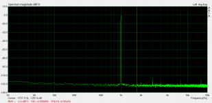
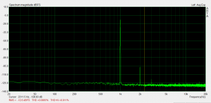
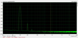
I made a small balanced to single ended converter on my breadboard to squeeze a bit more out of my focusrite 2i2 for measurements. Attached are 1K (hp) distortion test and 100Hz (lp) distortion test. predominantly 2nd harmonic as predicted by the sims. Not fantastic figures but not bad either.
I tested the hp at 9K as well and result was the same as for 1K
First pic is the loopback. 2nd high pass and 3rd low pass. Note that the HP has approx 6.5db attenuation.
Tony.
I tested the hp at 9K as well and result was the same as for 1K
First pic is the loopback. 2nd high pass and 3rd low pass. Note that the HP has approx 6.5db attenuation.
Tony.
Attachments
Thanks! ") It's been playing for a year!! I'm very happy with it. I did give up on trying to track down the low level noise in the low pass circuit, as I am not 100% sure whether it is inherent in the design, or just a measurement issue (due to the extremely low levels, a S/N ratio problem). In practice it does not appear to be having any negative impact on the sound.
It's been playing for a year!! I'm very happy with it. I did give up on trying to track down the low level noise in the low pass circuit, as I am not 100% sure whether it is inherent in the design, or just a measurement issue (due to the extremely low levels, a S/N ratio problem). In practice it does not appear to be having any negative impact on the sound.
I have considered revisiting this to do an opamp only based one. Using opamps configured as buffers in place of the B1's as I thought that may be more accessible, and in reality would probably have better objective performance (almost certainly lower distortion). It may even solve the lp "noise" issue. I have too many other incomplete projects to get through first though
Once I finish my DAC build I will have a better reference source, though to do any proper subjective comparisons would be difficult because I am not sure how I would reproduce the slopes I can do with this topology with a Sallen key filter, and you would need to ensure both circuits were giving identical transfer functions to determine if there were any inherent benefits or weaknesses in the design.
I suspect the ability to tailor the transfer function so easily probably makes up for any potential weaknesses in other areas (like slightly higher distortion) The good thing with the distortion profile is there are virtually no harmonics after 3rd (and third is very low anyway).
Tony.
It's been playing for a year!! I'm very happy with it. I did give up on trying to track down the low level noise in the low pass circuit, as I am not 100% sure whether it is inherent in the design, or just a measurement issue (due to the extremely low levels, a S/N ratio problem). In practice it does not appear to be having any negative impact on the sound. I have considered revisiting this to do an opamp only based one. Using opamps configured as buffers in place of the B1's as I thought that may be more accessible, and in reality would probably have better objective performance (almost certainly lower distortion). It may even solve the lp "noise" issue. I have too many other incomplete projects to get through first though
Once I finish my DAC build I will have a better reference source, though to do any proper subjective comparisons would be difficult because I am not sure how I would reproduce the slopes I can do with this topology with a Sallen key filter, and you would need to ensure both circuits were giving identical transfer functions to determine if there were any inherent benefits or weaknesses in the design.
I suspect the ability to tailor the transfer function so easily probably makes up for any potential weaknesses in other areas (like slightly higher distortion) The good thing with the distortion profile is there are virtually no harmonics after 3rd (and third is very low anyway).
Tony.
wintermute,
Gratifying to see you have not given up on it.
I was drawn to your idea since it paralleled my original intention which was to use LC filters between the Pass complimentary buffers. The inductor was impossibly noisy and I could not quiet it so when I saw your article and posts I thought THIS IS THE WAY!
Of course, as with all things, it is not perfect but it seems to me to get closer to that impossible goal than any other approach we have.
It is obvious that sound quality is your first priority so it would be really something if an op amp based buffer sounded better than either a first or second generation B1 buffer.
One good thing if using an op amp would be the ability to add gain to equalize the channels. Maybe those SPARKOS discrete op amps would get close to the B1? I guess BURSON's should be considered, too. Much easier for you to get those.
My fascination with the approach is limited by my ability to get it up and running without some hand-holding.
Would you be willing to post a schematic of your current setup with the frequency you have set? Something that could get me started and then I could manipulate the components to fit my needs. I will continue to think about what you have written.
I will be using ZEN MOD's diamond buffers with your scheme now that the DIYAudio store no longer has the matched pairs of FETs. I have a couple of the complimentary B1 buffers so maybe one of each? A low pass filter is my first priority.
Thanks,
Hi Rick, yes the original philosophy behind this was to be as transparent as possible, and to not use any opamps in the direct signal path. I chose the B1 because it was about the simplist non-opamp buffer I could find at the time
Attached is the as implemented schematic. Note that I went with 3rd order electrical (but non standard slopes) on both drivers, the values were determined using either the PCD spreadsheet or speaker workshop using actual drivers response and phase data, and tweaked to get the best response and phase matching. Once you have the passive circuit it is easy to translate those values to the resistors and caps for the actual "active" circuit.
The passive circuit values calculated were as follows:
HP. Load resistor 6.19K 47nF first cap 2.4H shunt coil, 200nF second cap.
LP 226mH first coil, 7.68uF shunt cap, 57.6 mH second coil.
This post has graphs of the transfer function of the filters http://www.diyaudio.com/forums/analog-line-level/164886-synergy-active-crossover-6.html#post4601485
This post has some additional explanation, and also some links http://www.diyaudio.com/forums/analog-line-level/164886-synergy-active-crossover-6.html#post4602288
Hopefully looking at the schematic makes it easy to see how the resistors and caps are translated from the passive implementation. The LP circuit has an effective load of 1 ohm. That cannot be changed. But when simulating 100 ohms works a lot better. You need to scale the component values accordingly Divide caps by 100, multiply coils by 100
C1, C13 and R6 for HP correspond to the mentioned passive circuit
R4, R13, R12 for the LP correspond to the mentioned passive circuit.
These are the only values that normaly would need changing for different slopes or crossover points, with the exception that you can change the load resistance in the HP (within reason) if it helps I found distortion performance in the sims was best with 47nF as the first cap, so played with load resistance so I could get that value for the first cap for my chosen crossover point (nominally 270 Hz)
If you have a passive circuit already and need help just let me know
The key in my opinion, is having good driver data to do sims so that the response can be tailored just as it would be in a passive implementation.
Tony.
Attached is the as implemented schematic. Note that I went with 3rd order electrical (but non standard slopes) on both drivers, the values were determined using either the PCD spreadsheet or speaker workshop using actual drivers response and phase data, and tweaked to get the best response and phase matching. Once you have the passive circuit it is easy to translate those values to the resistors and caps for the actual "active" circuit.
The passive circuit values calculated were as follows:
HP. Load resistor 6.19K 47nF first cap 2.4H shunt coil, 200nF second cap.
LP 226mH first coil, 7.68uF shunt cap, 57.6 mH second coil.
This post has graphs of the transfer function of the filters http://www.diyaudio.com/forums/analog-line-level/164886-synergy-active-crossover-6.html#post4601485
This post has some additional explanation, and also some links http://www.diyaudio.com/forums/analog-line-level/164886-synergy-active-crossover-6.html#post4602288
Hopefully looking at the schematic makes it easy to see how the resistors and caps are translated from the passive implementation. The LP circuit has an effective load of 1 ohm. That cannot be changed. But when simulating 100 ohms works a lot better. You need to scale the component values accordingly Divide caps by 100, multiply coils by 100
C1, C13 and R6 for HP correspond to the mentioned passive circuit
R4, R13, R12 for the LP correspond to the mentioned passive circuit.
These are the only values that normaly would need changing for different slopes or crossover points, with the exception that you can change the load resistance in the HP (within reason) if it helps
I found distortion performance in the sims was best with 47nF as the first cap, so played with load resistance so I could get that value for the first cap for my chosen crossover point (nominally 270 Hz)If you have a passive circuit already and need help just let me know
The key in my opinion, is having good driver data to do sims so that the response can be tailored just as it would be in a passive implementation.
Tony.
Attachments
Last edited:
wintermute,
Thanks for your time and advice.
I am trying to fully understand the workings of this device. I do not mind telling you it is over my head. But it is the kind of thing that once I have something working and start working with it I will have an easier time.
Wish I could sim things. I did download the TI Spice thing yesterday and am starting to get a feel for it. Long way to go ...
At the moment I am using a RCRC filter between two of the Pass complementary buffers and this works so much better than a choke and cap at the speaker. There is a big insertion loss. I am using 1:5 autoformers in the input of the amps to regain the level. At the moment I am only concerned with low pass since my above 400 hz amps use input and output caps. I have selected values there to get the crossover slope I need. So far all seems to work well with second order but I will eventually want to try something steeper.
I would like for a LC filter between the buffers (sounds like a ROLLING STONES album) to be quiet. I found some chokes from a UK company called CARNHILL which are made for mixing boards and hope they might be intrinsically quieter than the chokes I asked Dave Slagle to make for me. I prefer passive components just because they are easy but if this is another dead end I will go with op amps.
Did you end up making PCBs? Do you have any of them left by any chance?
Hi Rick, yes I do have some boards (had to order minimum 10) send me a pm if you would like a couple (only one channel per board).
You could make up just the GIC parts and feed in from your own buffers. or you could build with the dc-b1's on board.
Note that there are 10 2sk170's per board, and to get low dc offset they should be 5 matched pairs. I don't have any caps on the output but if offset was high you could add a coupling cap.
Power supply +10 -10 though if you were just doing the gic part you could use whatever the opamps are happy with.
The 10 pairs of matched fets was what was making me think an opamp based version may be more accessible to the average diy'er I found I had simmed one, and distotion was indeed a lot lower for the HP session with a good opamp for the buffer. But I like it with the fets
oh and the last point. There are a few smd components on the boards. Two 0805 caps (27pf) necessary to stop the oscillation in the LP section, and four 1206 decoupling caps on the opamps. I managed to solder them all just using a normal iron and a magnifying glass. The 0805's are pretty tricky but doable.
Tony.
send me a pm if you would like a couple (only one channel per board). You could make up just the GIC parts and feed in from your own buffers. or you could build with the dc-b1's on board.
Note that there are 10 2sk170's per board, and to get low dc offset they should be 5 matched pairs. I don't have any caps on the output but if offset was high you could add a coupling cap.
Power supply +10 -10 though if you were just doing the gic part you could use whatever the opamps are happy with.
The 10 pairs of matched fets was what was making me think an opamp based version may be more accessible to the average diy'er
I found I had simmed one, and distotion was indeed a lot lower for the HP session with a good opamp for the buffer. But I like it with the fets oh and the last point. There are a few smd components on the boards. Two 0805 caps (27pf) necessary to stop the oscillation in the LP section, and four 1206 decoupling caps on the opamps. I managed to solder them all just using a normal iron and a magnifying glass. The 0805's are pretty tricky but doable.
Tony.
Hi Rick, from what I have been able to work out, the Open Loop Gain of the opamp seems to be the most important aspect for stability and performance in the Low pass FDNR. The two opamps I have successfully used have been OPA2134's and LM4562's (both work fine in the HP as well).
The 627 has a lower OLG at around 110-120 compared to the LM4562, but it is around the same as the the opa2134. The lm4562's are around 140.
The 627 may be more fussy about the layout (not to mention they are expensive!!)
You could try them, but no guarantees as to how they would perform. You may get oscillations if the 627's don't like the circuit and they don't sound good!!
The LM4562's are less than $4, and would be my choice (there is very little difference in circuit between the two). The OPA2134's are a little over $4.
I know that OPA2604's do not like this FDNR circuit at all. No matter what I tried I could not make them stable.
Tony.
The 627 has a lower OLG at around 110-120 compared to the LM4562, but it is around the same as the the opa2134. The lm4562's are around 140.
The 627 may be more fussy about the layout (not to mention they are expensive!!)
You could try them, but no guarantees as to how they would perform. You may get oscillations if the 627's don't like the circuit
and they don't sound good!! The LM4562's are less than $4, and would be my choice (there is very little difference in circuit between the two). The OPA2134's are a little over $4.
I know that OPA2604's do not like this FDNR circuit at all. No matter what I tried I could not make them stable.
Tony.
I may be wrong, but in this application where the opamps are in a shunt configuration, ie the signal is not passing "through" the opamp, I suspect that the very high spec audio opamps are probably overkill, however if they work and work well then why not! It's worth a try, they may perform better than either of the two that I've had success with!
Tony.
Tony.
I may be wrong, but in this application where the opamps are in a shunt configuration, ie the signal is not passing "through" the opamp, I suspect that the very high spec audio opamps are probably overkill, however if they work and work well then why not! It's worth a try, they may perform better than either of the two that I've had success with!
Tony.
yes, you may be wrong...I have not read the whole thread, but...every stage in amplification is amplifying what signal went to the ground. So whatever you believe is not in signal path, may actually affect sound significantly.
This is from lampizators old pages (and I believe it):
I read about signal path so many times I am almost ready to believe it. Short signal paths, pure s.p., elegant s.p. silver wire in s.p. you name it. I am sure everybody knows what I am talking about.
The bitter truth is IT IS NOTHING LIKE what people think it is. The so called "signal" does not flow along some PATH. Lets take a pre amp for an example. The signal (current) enters via RCA jack, and the first thing it sees is usually a parallel resistor or some kind of parallel pot. The signal sinks to the ground through this resistor and that's all. Yes. The journey is over. It is like the movie hero who dies in the first scene. Hard to believe?
Having said that - lets agree once and for all - the CURRENT flows, and the VOLTAGE IS. The voltage does not flow.
The Waves PROPAGATE in circuits but they happen everywhere at the same time and involve all circuits.
The minuscule current flowing from your CD source to the ground via this parallel impedance of a mentioned pot produces small voltage resulting from the impedance of the pot (Ohm's law) This voltage is then being "read" by the grid electrode of the tube, or in non-hifi units - the base of transistor, and this signal in turn regulates the series impedance of the active element. The electricity from power supply then copies the original signal in what we call "amplification stage". So this is a copy, not the original. Signal path is a myth. The VOLTAGE - does not flow by definition. The voltage IS. The current flows. But it does not flow from source to the load (receiver). The current flows from power supply to the ground via active elements. In every STAGE of amplification the current flows in VERTICAL manner, not "horizontal". If an amp has 3 stages, there will be 3 cases of current flowing from PSU to ground by the active part. So path is from PS to ground, not from CD to speakers. Once we understand it - it is easier to talk further.
Another thing is timing of signal - it does not go from one place to another. The WHOLE CIRCUIT responds to signals instantly, the whole event HAPPENS. It does not flow. The circuit response is everywhere at the same time, all elements at the same time. No flow. Input receives - output responds. At the same moment.
...and more
Oh I heard it so many times. "In this crossover network use premium caps in series with the driver, but the coil is ONLY (!) parallel so it is unimportant. And this parallel cap can be WIMA el cheapo because it is not in the path." PUHLEEZE! People think of the electricity as a row of ants marching through a path. The series component must be good because they walk on it like over a bridge. Parallel components are like road signs on the side of the path, They are there, but don't affect the "marching process". NOT TRUE.
Electricity is an electromagnetic energy propagating through the network, NOT marching ants. The parallel components distort the signal THE SAME WAY AND THE SAME AMOUNT as parallel.
Imagine a sheet of paper. A4 on this side of Atlantic. Now tear it in half. Which torn part has more distorted edge??? See? Both equally. Because what is removed takes away from the whole some amount of distortion, or what stays- leaves some distortion. No difference. Mathematically speaking there is no difference between the effect that on the mathematical equation has the application of say z=jwc or z=1/jwL. For example, if you open a series cap and if you short the parallel coil in second order filter the result is THE SAME. No signal. 100% distortion ! ;-)
Still don't believe me?
OK. The coil in parallel application of second order network is not really parallel to the signal. It is in series! Yes. The current from amp flows through the speaker wire, through the series cap, and through the parallel coil to earth. This current produces over the coil's impedance some voltage proportional to the impedance (reactance) of coil with ALL ITS DISTORTION COMPONENTS and this voltage is fed to the driver.
Does it still look unimportant?
I think you have over-reacted to what wintermute wrote.
I think everyone knows that every element in a circuit has an effect. The question is whether the shunt elements are as affecting as series elements. I think of the shunt regulator as an example. There seems to be agreement than the shunt style is better than series. Sure they both take their tolls but the shunt is better in comparison.
The idea behind this project was to do away with the positive feedback of the SALLEN KEY filter. There is little doubt in my mind that wintermute's approach is better than the SALLEN KEY.
His language can be accused of being simplified to make the main point of his argument easy to understand. I think most of us know that what you say is a GIVEN. There is no doubt that everything in a circuit is involved. The question is which pieces are the most destructive to the final result. All of the elements are not destructive to the same degree. The trick is finding where the pitfalls are. Compromise being the implacable foe of all audio gear obsessions makes it own demands. I think wintermute has done a good job of balancing these competing desires for perfection in hiscircuit.
I know I look forward to hearing what this approach can do.
At the moment using a RCRC network between two buffers which does lose lots of signal but sounds great. Would like to get that lost signal back!
Hi Adason, there is a LOT to read It has been quite a journey. No arguments around anything shunting to ground also can have an effect on the sound, Rick pretty much nailed it though, my assertion is that it should probably have less effect than if the device was being used as a buffer or gain stage. It's more of a philosophical argument than a scientific one There was a reason I put through in quotes The signal is still being modified by the opamps in this circuit, just they are doing it in a less direct manner, which is philosophically more audiophile friendly
I have found through simulation, and actual tests, that some opamps behave MUCH better in this circuit than others, and it hasn't been parameters usually associated with better audio performance that have made the difference (eg slew rate and GBW seem to have little effect on how well the circuit works). High Open Loop Gain seems (from what I can tell) to be the most important parameter. I also suspect phase margin is important.
The FDNR is a simple looking, but very complex circuit, and I'd be lying if I said I understand how it works at an electrical level!! I think the most important thing for it is finding a device that works well in that role. I'm just a hobbyist and have arrived here through simulation and experimentation, someone with a much deeper understanding than I have could probably improve this a lot.
The GIC on the high pass is a different beast and seems to be very stable and not finicky at all, and experimenting with different opamps in that part of the ciruit could potentially be rewarding. It has worked with everything I have tried in it, which I think is opa2134, opa2604, LM4562, and I think I may have even tried a TL072!
Because of the finicky nature of the LP section, and this being primarily what Rick is interested in, I thought it may be best to start out with something I know works. Otherwise he may try with the 627's and not get a good result (It sounds terrible with the opa2604's due to the oscillation problems with that chip in this circuit).
Tony.
It has been quite a journey. No arguments around anything shunting to ground also can have an effect on the sound, Rick pretty much nailed it though, my assertion is that it should probably have less effect than if the device was being used as a buffer or gain stage. It's more of a philosophical argument than a scientific one There was a reason I put through in quotes The signal is still being modified by the opamps in this circuit, just they are doing it in a less direct manner, which is philosophically more audiophile friendly I have found through simulation, and actual tests, that some opamps behave MUCH better in this circuit than others, and it hasn't been parameters usually associated with better audio performance that have made the difference (eg slew rate and GBW seem to have little effect on how well the circuit works). High Open Loop Gain seems (from what I can tell) to be the most important parameter. I also suspect phase margin is important.
The FDNR is a simple looking, but very complex circuit, and I'd be lying if I said I understand how it works at an electrical level!! I think the most important thing for it is finding a device that works well in that role. I'm just a hobbyist and have arrived here through simulation and experimentation, someone with a much deeper understanding than I have could probably improve this a lot.
The GIC on the high pass is a different beast and seems to be very stable and not finicky at all, and experimenting with different opamps in that part of the ciruit could potentially be rewarding. It has worked with everything I have tried in it, which I think is opa2134, opa2604, LM4562, and I think I may have even tried a TL072!
Because of the finicky nature of the LP section, and this being primarily what Rick is interested in, I thought it may be best to start out with something I know works. Otherwise he may try with the 627's and not get a good result (It sounds terrible with the opa2604's due to the oscillation problems with that chip in this circuit).
Tony.
yes, I have not read full thread, I admit...
you may find this interesting about opa2604...all it needs is lower power supply
http://www.diyaudio.com/forums/parts/295854-opa2604-dead.html
you may find this interesting about opa2604...all it needs is lower power supply
http://www.diyaudio.com/forums/parts/295854-opa2604-dead.html
wintermute has synthesized many good ideas into his scheme.
I have to say adason's fulminations are refreshing - too many folks around here want to convince people that nothing much matters other than the topology. In fact with too many of them I wonder just what kind of audio experience they are working towards. Most of the time I think they spend more time on responding to posts than listening to music.
So when someone gets excited about how everything does influence what we hear it makes me happy.
Rick, there is no free lunch with GIC's .
From another thread: http://www.diyaudio.com/forums/analog-line-level/289404-transforms-using-sallen-key-topology-2.html
From another thread: http://www.diyaudio.com/forums/analog-line-level/289404-transforms-using-sallen-key-topology-2.html
Not sure why you think I think there is a free lunch!
I think wintermute's scheme is one I need to hear for myself.
At the moment I am using a rcrc filter between two buffers (using Linear Systems FETs) that sounds really good to me. I have ordered a choke to try an rlc. The choke is made by a UK company that makes parts for mixing consoles. I have attempted to use chokes before and could not control the noise. I am hoping this one has some inherent noise avoidance!
The rcrc has so much insertion loss I have to use a 1:5 autoformer to match levels. I prefer an autoformer within a limited frequency range to an active gain stage. The driver in question is being used between 100 and 400 Hz.
My audio hero is Salvador Dali who said to not fear perfection since you will never achieve it. No free lunch is another given!
I had tried SK filters but was never satisfied. Went back to speaker level components and then I took room measurements and saw what a mess I had due to the interaction of the choke and the horn loaded woofer. With no choke there is no comparison (to using a choke at the speaker) in what the measurements show and what my ears hear. Thankfully there is correlation.
So I want to compare the three: rcrc, lrc and the GIC. Certainly the GIC offers more flexibility but an active element is an active element no matter where it is placed in the circuit. Will be edifying to hear which one I find the most satisfying.
Hoping others will join in trying the SYNERGY approach.
- Status
- This old topic is closed. If you want to reopen this topic, contact a moderator using the "Report Post" button.
- Home
- Source & Line
- Analog Line Level
- The Synergy "Active" Crossover