Hi James, that is the passive network that would be required to get the 4th order bessel slope (at 250Hz) I'm after with a 1 ohm resistive load.
The 1 ohm load is basically what is used to simplify the filter calculations for the active implementation. It is basically hypothetical, but a means to an end")
The passive crossover for the MTM I've posted here http://www.diyaudio.com/forums/multi-way/68301-my-morel-mtm-project-7.html#post2740332 The baffle step is in the form of a Notch filter (at about 1.2Khz) rather unconventional (when am I not) but does the trick nicely It has a really flat response when out in the open.
post 140 in that thread http://www.diyaudio.com/forums/multi-way/68301-my-morel-mtm-project-7.html#post2776367 has measurements of the the completed crossover, and a comparison of the SIM'ed response compared to the actual.
There is a bit of a hump between around 300 and 700 Hz in the mtm's in room response so I'm correcting for that in the crossover. It may be a dumb idea, maybe not. Perhaps I should try running the sim with the measurements I did outside and see what the result is
edit: added sim with outside measurements (ones that I wasn't particularly happy with) quite different, and if I tried to design with these then I suspect I would end up with very bass heavy speakers once room gain was taken into account.
Tony.
The 1 ohm load is basically what is used to simplify the filter calculations for the active implementation. It is basically hypothetical, but a means to an end
The passive crossover for the MTM I've posted here http://www.diyaudio.com/forums/multi-way/68301-my-morel-mtm-project-7.html#post2740332 The baffle step is in the form of a Notch filter (at about 1.2Khz) rather unconventional (when am I not) but does the trick nicely
It has a really flat response when out in the open. post 140 in that thread http://www.diyaudio.com/forums/multi-way/68301-my-morel-mtm-project-7.html#post2776367 has measurements of the the completed crossover, and a comparison of the SIM'ed response compared to the actual.
There is a bit of a hump between around 300 and 700 Hz in the mtm's in room response so I'm correcting for that in the crossover. It may be a dumb idea, maybe not. Perhaps I should try running the sim with the measurements I did outside and see what the result is
edit: added sim with outside measurements (ones that I wasn't particularly happy with) quite different, and if I tried to design with these then I suspect I would end up with very bass heavy speakers once room gain was taken into account.
Tony.
Attachments
Well it's together... something is not quite 100% as the crossover point is coming in at 217Hz. I think that there is something wrong with my Spice sim, because the LP had about 3db drop compared to the HP in the sim, but the real world measurement shows virtually identical levels (within 0.1db (unless of course the default setting of the pot, coincidentally sets the levels exactly equal).....
The instability is back with the 3rd order filter implementation in the LP section, but I had to increase my resistors from 5K to 20K in the sim to get it not to oscillate, (which I haven't done yet on the board... wanted to see if it was necessary)... SO I guess I should do that.
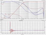
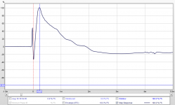
Attached is the holm impulse plot of low and high pass. Again this is a deliberately misalinged filter slope, so if it looks a bit off it is
I might give it a listen (one channel) as is. I'm really curious to see how it sounds!
Tony.
The instability is back with the 3rd order filter implementation in the LP section, but I had to increase my resistors from 5K to 20K in the sim to get it not to oscillate, (which I haven't done yet on the board... wanted to see if it was necessary)... SO I guess I should do that.
Attached is the holm impulse plot of low and high pass. Again this is a deliberately misalinged filter slope, so if it looks a bit off it is
I might give it a listen (one channel) as is. I'm really curious to see how it sounds!
Tony.
Attachments
listen in mono was good No noise (other than the usual hum I have which comes from the community antenna)
First impression was that something was missing. (the hump taken out in the 300-700 hz range) but after a short while, my brain got used to that and it sounded better than ever
The 10" is blending with the MTM nicely. It's quite surprising actually just how little there is below 200Hz. What is also interesting is that even though my poor old 70L 10" cabinets are a bit boomy, the bass still sounds punchy... There is quite a bit of the bass impact (drums) above 200Hz which surprised me.
Definitely am going to have to make some new cabinets for the woofers, but even without doing that, first impression is that it is an improvement over the MTM's on their own and this is without having done any level setting (I suspect I could dial the HP down just a touch).
Will do an in room measurement hopefully tomorrow evening (though I don't expect a great correlation with the sim as only one side is running).
Tony.
No noise (other than the usual hum I have which comes from the community antenna) First impression was that something was missing. (the hump taken out in the 300-700 hz range) but after a short while, my brain got used to that and it sounded better than ever
The 10" is blending with the MTM nicely. It's quite surprising actually just how little there is below 200Hz. What is also interesting is that even though my poor old 70L 10" cabinets are a bit boomy, the bass still sounds punchy... There is quite a bit of the bass impact (drums) above 200Hz which surprised me.
Definitely am going to have to make some new cabinets for the woofers, but even without doing that, first impression is that it is an improvement over the MTM's on their own
and this is without having done any level setting (I suspect I could dial the HP down just a touch). Will do an in room measurement hopefully tomorrow evening (though I don't expect a great correlation with the sim as only one side is running).
Tony.
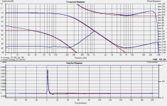
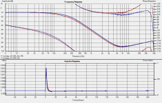
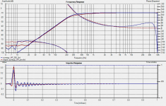
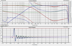
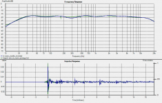
OK so the spice sim lied where I thought I had to adjust the values in the LP section to match the speaker workshop sims curve, in reality the original value was ok. I substituted the 24K resistor for an 18 (passive sim says 17.5K) and now the LP is very close to simmed value. First pic shows the actual vs the sim.
2nd pic shows what I had last night vs now (now is blue).
The HP is also off, though I'm not sure what is happening there.. not as easy to diagnose. It looks more like a normal rolloff. Blue is measured the other is the sim. Putting in a bigger cap 41nf instead of 33nf, which is about 20% over does make the sim more like the actual value so it could be my cap is higher than it should be (cheap jaycar mkt for the test). The more concerning (perhaps) is the ringing in the impulse response. Not sure what that means... Blue is the measured result.
Tony.
where I thought I had to adjust the values in the LP section to match the speaker workshop sims curve, in reality the original value was ok. I substituted the 24K resistor for an 18 (passive sim says 17.5K) and now the LP is very close to simmed value. First pic shows the actual vs the sim. 2nd pic shows what I had last night vs now (now is blue).
The HP is also off, though I'm not sure what is happening there.. not as easy to diagnose. It looks more like a normal rolloff. Blue is measured the other is the sim. Putting in a bigger cap 41nf instead of 33nf, which is about 20% over does make the sim more like the actual value so it could be my cap is higher than it should be (cheap jaycar mkt for the test). The more concerning (perhaps) is the ringing in the impulse response. Not sure what that means... Blue is the measured result.
Tony.
Attachments
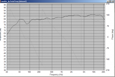
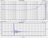
ok false alarm the ringing is at a high frequncy, approx 48Khz, and is inherent to the soundcard. attached is the loopback measurement. phew!
Most likely an AD artifact at or about the nyquist freq.
Also something I forgot to mention last night is that there is as good as zero insertion loss as well something that was worrying me from the spice sims.
The second attachment shows the loopback measurement along with the low and high pass measurements. All taken at -10db in holm impulse.
Tony.
the ringing is at a high frequncy, approx 48Khz, and is inherent to the soundcard. attached is the loopback measurement. phew!Most likely an AD artifact at or about the nyquist freq.
Also something I forgot to mention last night is that there is as good as zero insertion loss as well
something that was worrying me from the spice sims. The second attachment shows the loopback measurement along with the low and high pass measurements. All taken at -10db in holm impulse.
Tony.
Attachments
OK so I decided to try something else today. Some RF filtering. I had seen what looked like AM RF at around 1Mhz on the scope before which the FDNR seems to amplify.
I did the calcs and 1nf to ground after the 220 ohm gate stoppers is pretty good (for a test) frequency starts to rolloff at around 50Khz and the corner frequency is around 250Khz. I actually put two in. one before the first buffer, and one before the LP buffer.
It works. It doesn't completely eliminate the noise but it shows that this is most likely what it is. Unfortunately in a real world implementation (rather than my test bench) it isn't quite so simple, as the volume control, and the level control I have on the high pass, WILL affect the corner frequency if not full on.
Probably the best place for an RC of this type is between the first buffer and the other two, that's not easy to pull off with the current board... Luckily however, I think it is pretty much a mute point, as it is so far below the levels as to be basically inaudible anyway I suspect. I will probably being the obsessive person I am eventually eliminate it, but for now I am happy to have found the cause.
First pic shows the difference with and without the filtering. Without is the lower trace. you can see it is quite a bit more ragged.
2nd pic shows distortion performance of the Low pass compared to the Sound card (blue trace). The lower lines are the THD.
3rd pic shows the ditortion performance of the High pass. I'm uncertain how to interpret this one. It is pretty much the same as the card at higher frequencies, but rising as the filter kicks in. I don't know if this is holm assuming that the lowering level is distortion. This is exactly the opposite of what the LP shows, where as the filter kicks in the distortion (for a while) actually drops to levels below that of the sound card in loopback... Me thinks some oddities in Holm's distortion analysis.
Anyway in the listening test I did before distortion wasn't something that I noticed
Tony.
Attachments
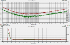
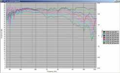
I also did some in room measurements. Perhaps my sim and values were not as successful as hoped... Though to be fair the measurements for the sim sim were done with both MTM's running, and both woofers running.
first plot is with left mtm and left woofer. Blue is the combined response. red is Just the MTM's (original dual measurement not the single one).
second plot was seeing what I would get if I ran the left MTM with the right woofer. Obviously there is a room node at 40Hz which is excited with this mic position and the right woofer running! Interesting I didn't get anywhere near that level when I ran both woofers, perhaps when both running they are smoothing out the room response.
I might have to try some new outside measurements as the ones I had before I was not happy with.
edit: graphs are 1/3 octave smoothed.
Tony.
Attachments
Last edited:
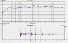
SO I remembered that the sim was done with 1 octave smoothing. I exported the sim and imported into holm impulse. The correlation is better than I thought. Slightly more dip around 300Hz. No doubt due to not summing as well as in the sim. If I use this approach, it looks like I need to try the high smoothing to get an initial solution and then go to perhaps 1/8th octave measurements to so the final tweaking.
Still I think I shall do some more outside measurements. Blue is the actual in room measurement.
Tony.
Still I think I shall do some more outside measurements. Blue is the actual in room measurement.
Tony.
Attachments
Last edited:
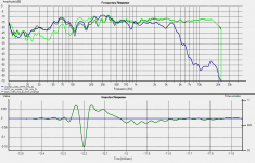
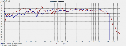
I did some measurements outside this morning. Attached is 1/8th octave smoothed. I can't get good data below 200Hz unfortunately. I'm pretty sure the mess around 100Hz is reflection related, probably ground bounce.
Blue trace is the woofer, Bright green is the MTM, and dark green is the two playing through the synergy.
It looks like a little bit of attenuation of the high pass would be good. I'll see if I can use these measurements in the sim to get a good correlation. Overall not too bad a result I guess.
It is interesting that I need to invert the woofer, or the MTM to get the best response, as in the sim no inversion was necessary... me thinks my in room measurements were a bit suspect!
I gated the whole thing at 70Hz which included some reflections which mostly affected the upper frequencies, then I loaded this into speaker workshop and 1/8th octave smoothed it. This seems to give a reasonable representation of the frequency response down to 70Hz. This is the second attachment.
I now reaslise why I had problems with the outside measurements. The baffle step is really obvious for the woofer, however in room the room gain makes the woofer pretty much at the same level as the MTM's.
Tony.
Attachments
I see you've been putting some time into this project, Tony!
I think you're trying to do 2 things at once here and you initially need to check the phase of the signal response at the Xover point for each driver and then check for correct alignment (voice coils/dustcaps/etc) - one thing at a time - the MTM comes first and maybe need some 'packers' under the tweeter for correct time alignment - MTMs can be quite tricky here and often easier to do it 'by ear' rather than rely totally on response/phase measurements
Then do the same with the bass driver, assuming the phase of the signal to the amps is in phase, or 180* inverted, and the amps themselves don't add some arbitrary varying amount too - it does happen, unfortunately.
How do you get a baffle step effect with the bass driver?
You have to set the filters in the measurements to cutoff the reflected signals if doing the driver response measurements as a single peak/dip of about 10dB will throw everything out - room response is a separate thing after the xover/speakers are done
Can you put your CRO on the high pass filter to make sure the filter/gyrator isn't creating the noise (oscillation) itself?
Ah, I may not have explained myself fully The MTM is going to remain with a passive crossover, it is only the crossover between the MTM and the 10" vifa that I am going active with
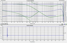
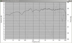
The MTM is pretty well sorted. attached are measurements I did a while ago. SPL and step response. I've only just become aware that I can get the step response in REW, and I think I have some idea how to interpret it. From it I would say that I have close to, but not quite time alignmemt between my tweeter and woofers.
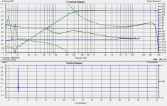
The FR on axis is really quite flat, and the off-axis performance is good too (third pic, measurement done in a completely different, and less ideal location).
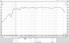
BUT I really am struggling with the measurements for doing this LP crossover. I'm starting to think I may have to accept my outside measurements gated at 200Hz and used nearfield measurements, baffle step corrected and spliced in using Jeff Bagbies response blender spreadsheet.
But that is the other thing that is bugging me... the baffle step.... The woofers are very close to the floor so get some boost because of that. That is not reflected in the measurements done outside.
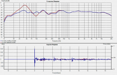
4th pic shows in-room dark green, vs outside, blue... note the significantly higher levels in the bass in the in room measurement... if I try and model based on the outside measurements I will end up with too much bass!
I did put the scope on it before. I DID have an oscillation at 1Mhz but only when using the opa2604. with the 2134 it is quite happy.. However I did get what appears to be AM signals, also around the 1Mhz mark, but these were present when the synergy was powered off, and the scope probes were just hanging in the air.. what I did find was that they were bigger in amplitude in some parts of the fndr around the opamp... so it can pick up AM, but I figure once it is properly shielded in a box this will probably be less of a problem. Also the level is very low, at around the 5 - 10 mV level.
Tony.
The MTM is going to remain with a passive crossover, it is only the crossover between the MTM and the 10" vifa that I am going active with The MTM is pretty well sorted. attached are measurements I did a while ago. SPL and step response. I've only just become aware that I can get the step response in REW, and I think I have some idea how to interpret it. From it I would say that I have close to, but not quite time alignmemt between my tweeter and woofers.
The FR on axis is really quite flat, and the off-axis performance is good too (third pic, measurement done in a completely different, and less ideal location).
BUT I really am struggling with the measurements for doing this LP crossover. I'm starting to think I may have to accept my outside measurements gated at 200Hz and used nearfield measurements, baffle step corrected and spliced in using Jeff Bagbies response blender spreadsheet.
But that is the other thing that is bugging me... the baffle step.... The woofers are very close to the floor so get some boost because of that. That is not reflected in the measurements done outside.
4th pic shows in-room dark green, vs outside, blue... note the significantly higher levels in the bass in the in room measurement... if I try and model based on the outside measurements I will end up with too much bass!
I did put the scope on it before. I DID have an oscillation at 1Mhz but only when using the opa2604. with the 2134 it is quite happy.. However I did get what appears to be AM signals, also around the 1Mhz mark, but these were present when the synergy was powered off, and the scope probes were just hanging in the air.. what I did find was that they were bigger in amplitude in some parts of the fndr around the opamp... so it can pick up AM, but I figure once it is properly shielded in a box this will probably be less of a problem. Also the level is very low, at around the 5 - 10 mV level.
Tony.
Attachments
The response that you've got going here is pretty impressive for an indoor/room response
- not sure about the 56.6dB level - a mis-label?
Is the second graph the step response of the MTM? What's it actually indicating?
The thing you've got about the bass driver being close to the floor is a bit of a puzzle - how hard is it to just lift it up higher?
Is there a reason that you can't simply raise the MTM higher and lift the bass driver below it?
My big boxes with the 12" drivers had to have a clear 4" space between box and floor to control the floor bounce - a right PIA in this small/med room - can't trap it out or use DSP for this as an acoustical problem
These gyrator filters are proving to be quite a challenge, eh!
Hi James, the measurements above are gated measurements taken outside, not in room. If they were in room I would be Very happy (the response is basically about +- 2.5db from 90 hz to about 18K) considering it is only intended to go down to around 250Hz I think that is pretty good). The only in room is the dark red trace in the fourth graph.
The step response shows the impulses from the mids and the tweeter in the MTM. I'm not sure which is which but I think that the fact that the first upward spike and the next downward spike are so close to the time zero that the two drivers are almost perfectly time aligned. basically within a few microseconds of each other. I zoomed in and it is actually about 37 microseconds, which is about 1.2cm
Now because of the fact that I may not be 100% spot on with my mic placement in the centre of the tweeter, and I probably was not properly in the farfiled (as the measurement was at 1.2M) I think 1.2cm as possible path length difference is within the measurement error range
The combo of MW144's surface mounted, with DMS37 tweeters flush mounted, is supposed to be time aligned (as advised to by Terry Paget, and I'm not going to try and second guess him!)
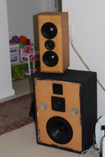
With respect to the bass driver being close to the floor, that is the current box design. I'm getting this going, with existing boxes, new boxes come later. The woofers act as the stand for the MTM's. to get the tweeter at listening height.
A picture is worth a thousand words, so here is what the current situation is. Only the woofer in use. Basically my old faithful threeways re purposed as dedicated woofers. The project to build some decent cabinets for the vifa's will come later (and a new round of crossover tuning when that happens).
Tony.
The step response shows the impulses from the mids and the tweeter in the MTM. I'm not sure which is which but I think that the fact that the first upward spike and the next downward spike are so close to the time zero that the two drivers are almost perfectly time aligned. basically within a few microseconds of each other. I zoomed in and it is actually about 37 microseconds, which is about 1.2cm
Now because of the fact that I may not be 100% spot on with my mic placement in the centre of the tweeter, and I probably was not properly in the farfiled (as the measurement was at 1.2M) I think 1.2cm as possible path length difference is within the measurement error range
The combo of MW144's surface mounted, with DMS37 tweeters flush mounted, is supposed to be time aligned (as advised to by Terry Paget, and I'm not going to try and second guess him!)
With respect to the bass driver being close to the floor, that is the current box design. I'm getting this going, with existing boxes, new boxes come later. The woofers act as the stand for the MTM's. to get the tweeter at listening height.
A picture is worth a thousand words, so here is what the current situation is. Only the woofer in use. Basically my old faithful threeways re purposed as dedicated woofers. The project to build some decent cabinets for the vifa's will come later (and a new round of crossover tuning when that happens).
Tony.
Attachments
Looks like the MTM is pretty well sorted - when everything's working well, small alignment distances become quite audible but something for another day ...
Bass driver - yes, having the driver this close to the floor is asking for trouble - just turn the damn thing upside down and get the bass driver closer to the MTM and away from the floor - might sound a bit thin tho - perhaps on it's side with a couple of spacers allowing free air flow below the box ...
I've started to see if I can get a better understanding of those FDNRs and plugging thru Rod Eliot's info - not the easiest circuit to follow - the simpler gyrator circuits are a lot easier to follow.
Yes Rod's comment that he isn't even going to try and go into how they work because they are just too complicated is a bit daunting... He also say's that other circuits can achieve the same thing much more simply.
Trust me to latch on to the most difficult to master filter type there is Unfortunately my tenacity is strong so I'm keeping on with it
Tony.
Trust me to latch on to the most difficult to master filter type there is
Unfortunately my tenacity is strong so I'm keeping on with it Tony.
It's a long time since I've had much to do with anything higher than 3rd order complex maths and this stuff is full of that - rather slow going - I can see where this SIM design avoids all this.
Yes, you could have chosen a simpler one anyway so wouldn't have to fight so hard against stability limits, phase and gain bandwidth, etc
I'm beginning to wonder if one of those simple non-feedback 12dB PLL filter Xovers sandwiched between a couple of dcB1 buffers would do a similar job - certainly a lot easier to manage, and I'm sure someone must have done this before ...
Yes I tried the calculation route initially, but could not get anything that worked. So I decided to cheat and use an online calculator for doing the filter (with the impedance set to one ohm) and then just did the scaling step
Putting the passive and the active into the sim allowed me to compare the results so that I knew I had something that was in the ball park!
Tony.
Putting the passive and the active into the sim allowed me to compare the results so that I knew I had something that was in the ball park!
Tony.
I remember this was a continuation of SY's valve xover that had a design fault/problem that you sorted out, if I remember correctly - so, yes, you do indeed have a lot of project stamina.
I went back to have a look at the "B1 Active Xover" (a Sallen Key project) and the other one with the passive, non-feedback filters called "Two B1 and a Crossover" which is similar to the one that you're designing just now -
I don't remember a pcb ever eventuating from the thread so I might have a short look at this to see what's involved when driven with shunt reg supplies, for example, to see if 2 layers are enough with maybe some links - will ignore the ground planes for the moment, but focus on supply lines, current flow and those tricky ground loops - maybe multiple cap donuts for pin sockets, etc
- just a look, mind you....
You wouldn't have a spare pair of the GR range of the jfets 2sk170/2sj74 by any chance?
I need a pair for a recent lower power Juma variation of the F5 (yes, another one) and looking for Id about 3.5mA - I have quite a few about 6.5mA and plenty above 7.5mA but none below - not sure if the A range (2.5 - 6.5mA) ones at diyAudio shop are actually at the low end or not - you get 8 for about $60 for the LSJ74s, not sure if close matched or not
Don't know who to ask about this - any clues? ....
Best person to get matched pairs from that I know is Spencer from fetaudio. though I think he only had BL parts...
I have one set only (2 pairs) of 2sk170/2sj74 which is for my BA3 frontend when I finally get around to building it matched at 10mA.
as far as I know the linear tech j74's are not direct drop-ins for the toshiba parts, so you might want to do some research there.
I'm pretty happy with the board now really. It is only my own implementation details that I am struggling with. If you want to pm me a postal address I can pop a pair of boards in the mail if you want to have a play
Doing a standard slope filter is dead easy, iether 2nd order, or third order. I can do the calcs if you want for the crossover freq you want.
Its the doing measurements and working out an ideal filter that has been consuming my time
Some objective (as in not the designers impressions) feedback would be good I really don't have anything to compare against since I haven't done any other form of active filter.
The error was in the maths on SY's home page. Had me scratching my head for quite a while, he assures me that the actual implementation had a proper 3rd order butterworth rolloff.
What I ended up with is quite different (apart from not being tube buffers). He used a standard Sallen Key for the low pass, and a more conventional gyrator for the HP (I used a GIC because it simmed better).
I read something somewhere a long time ago about problems with Sallen key (and I think I used some filter sim software as well) that gave me a bad impression, which is why I went the FDNR route. Was probably unfounded, but there you go. My second choice behind FDNR was state variable.
Tony.
I have one set only (2 pairs) of 2sk170/2sj74 which is for my BA3 frontend when I finally get around to building it matched at 10mA.
as far as I know the linear tech j74's are not direct drop-ins for the toshiba parts, so you might want to do some research there.
I'm pretty happy with the board now really. It is only my own implementation details that I am struggling with. If you want to pm me a postal address I can pop a pair of boards in the mail if you want to have a play
Doing a standard slope filter is dead easy, iether 2nd order, or third order. I can do the calcs if you want for the crossover freq you want.
Its the doing measurements and working out an ideal filter that has been consuming my time
Some objective (as in not the designers impressions) feedback would be good
I really don't have anything to compare against since I haven't done any other form of active filter.The error was in the maths on SY's home page. Had me scratching my head for quite a while, he assures me that the actual implementation had a proper 3rd order butterworth rolloff.
What I ended up with is quite different (apart from not being tube buffers). He used a standard Sallen Key for the low pass, and a more conventional gyrator for the HP (I used a GIC because it simmed better).
I read something somewhere a long time ago about problems with Sallen key (and I think I used some filter sim software as well) that gave me a bad impression, which is why I went the FDNR route. Was probably unfounded, but there you go. My second choice behind FDNR was state variable.
Tony.
Yes, those little jfets are getting a bit hard to find now - will keep on looking - understand there are some equivalents but not sure just how equivalent they really are, otherwise we'd all be using them, no?
I think the Sallen-Key method, if done really well, can be 'top sound' - I've just never heard it sound as good as the passive, non-feedback filters so I tend to be a bit more closed mind about it, particularly as high pass or band pass - other people seem to hear it otherwise and on different systems, it does perfectly to work pretty well
On low pass filters, the SK filters can be very useful so they're not a total write off - the biggest problem for me is either the poor implementation of ICs, and/or substandard pcb design including layout, components, etc.
I just noticed that the Pass B4 Xover apparently is now available - not sure if this is old news and can't quite remember what sort of filters are used.
The State variable filters are quite often used in Pro-audio with very mixed results - not a favourite of mine at all - can obtain great theoretical results but the 'good sound' is quite elusive, IMO
Those Behringer UltraDrives (2496) are a very useful gadget for sorting out Xovers in real time rather than theoretical but even with all the upgrades in the world, the sound quality just isn't 'it', IMO.
A very useful tool for design work and then the hard grind to convert into analogue filters and the patience to slowly get them 'right' ....
- Status
- This old topic is closed. If you want to reopen this topic, contact a moderator using the "Report Post" button.
- Home
- Source & Line
- Analog Line Level
- The Synergy "Active" Crossover