Hi,
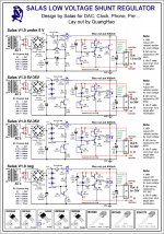
I built the 5 to 15V version. I will be feeding 5 volts. The problem is that I'm not sure for my exact target current. The shunt will be used for supplying the DAC analog part. The chip is AK4396. On the datasheet it's said 32mA typical and 47mA max current. So how to make as constant voltage as possible? Increase output current using the load resistor?
built the same reg for same chip. Just to confirm, if I'm aiming at 100mA output and have 9.5v after rectification, R1 should be 9.5 Ohm, right? I wonder how it was calculated in other cases (att.)?
Attachments
Hi Salas.
I'd love to build one of your single-rail positive Salas Shunt Regs to power my (original version, not DCB1) Pass Labs B1 buffer. So I guess around 22-24V required.
There's a bewildering amount of schematics in this (nearly!) 500 page thread. I'd be greatful if you could point me towards the latest/best schematic to use for my B1.
Many thanks")
- John
I'd love to build one of your single-rail positive Salas Shunt Regs to power my (original version, not DCB1) Pass Labs B1 buffer. So I guess around 22-24V required.
There's a bewildering amount of schematics in this (nearly!) 500 page thread. I'd be greatful if you could point me towards the latest/best schematic to use for my B1.
Many thanks
- John
Hi Salas.
I'd love to build one of your single-rail positive Salas Shunt Regs to power my (original version, not DCB1) Pass Labs B1 buffer. So I guess around 22-24V required.
There's a bewildering amount of schematics in this (nearly!) 500 page thread. I'd be greatful if you could point me towards the latest/best schematic to use for my B1.
Many thanks
- John
John, hi!
Fellow Briton KatieandDad had shown a combination like the one you have in mind rather recently and reported favorably. He had used a normal B1 fed from the DCB1's PSU section only. Since its a beaten path I am tempted to suggest you repeat that combo.
Here is the business end you need. Just use 10 leds for the shown row of 5. Feed it >7V than its output. R4 & R5 are check points for local currents that you may skip or not. We will be happy to learn about your progress and result.
Cheers
Attachments
9.5V is too close to 5V.
You have been told repeatedly that the Salas Style regulator needs ~7V across the reg to work properly.
That also applies when varying input voltage becomes available.
sorry, Andrew, with all regards, I didn't get your post at all. What R1 should be in my case to gain on output 80-100mA?
9.5V is too close to 5V.
9.5 - 5 = 4.5I didn't get your post at all.
That is far too low to meet the >=7V requirement for the voltage drop across a Salas Style Shunt Regulator.
Measurement purpose only! Thanks Salas
battery charger
hello all,
i drew a minimalist battery charger while waiting for parts for the jfet CCS SSLV3.3V i am playing with.i m also trying to find P mosfet to allow the use of 1 battery pack for several regs.
please consider that this is merely an attempt to create a charger. i am not an EE.
the charger section was design taking bits from the lm317 datasheet and the rest is my creation.
it can accept any battery type.
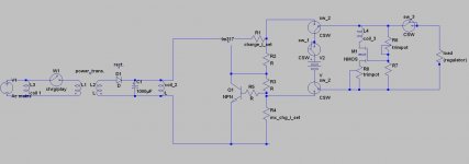
there is an optional protection circuit for lithium types. if the battery voltage falls below a certain voltage set by R6, M1 shuts down and only a tiny current runs through the divider. r8 sets the relay coil_3 current. for around 6V-7V battery operation, use a high Vgs high Yfs fet like irf540, r6=1M r8 =100R and a 3Vdc (or so) relay.
as drawn, the circuit is playing music. if you close the power switch, it turns to charge state. some circuit parts are to be determine because they depend on the charge voltage and charger can be found if you look at the datasheet. the charger has a current limiter and the current diminishes until the battery reaches the desired voltage where no current will flow.
personally, i m a bit concern that coil_1 may induce noise in the circuit. maybe a separate dc coil with own small main trafo and rectifier always on is a good alternative?
notes:
-coil_1 is there relay coil to sw_1, etc.
-capacitor better be a high endurance type like nichicon HE
- you can parallel charge circuit to charge batteries individually and the protection circuit can be adapted to ''monitor'' lithium cells individually.
if you have any suggestion, comments, questions or concerns, please express yourself.
if you see any nonsense, just tell me
hello all,
i drew a minimalist battery charger while waiting for parts for the jfet CCS SSLV3.3V i am playing with.i m also trying to find P mosfet to allow the use of 1 battery pack for several regs.
please consider that this is merely an attempt to create a charger. i am not an EE.
the charger section was design taking bits from the lm317 datasheet and the rest is my creation.
it can accept any battery type.
there is an optional protection circuit for lithium types. if the battery voltage falls below a certain voltage set by R6, M1 shuts down and only a tiny current runs through the divider. r8 sets the relay coil_3 current. for around 6V-7V battery operation, use a high Vgs high Yfs fet like irf540, r6=1M r8 =100R and a 3Vdc (or so) relay.
as drawn, the circuit is playing music. if you close the power switch, it turns to charge state. some circuit parts are to be determine because they depend on the charge voltage and charger can be found if you look at the datasheet. the charger has a current limiter and the current diminishes until the battery reaches the desired voltage where no current will flow.
personally, i m a bit concern that coil_1 may induce noise in the circuit. maybe a separate dc coil with own small main trafo and rectifier always on is a good alternative?
notes:
-coil_1 is there relay coil to sw_1, etc.
-capacitor better be a high endurance type like nichicon HE
- you can parallel charge circuit to charge batteries individually and the protection circuit can be adapted to ''monitor'' lithium cells individually.
if you have any suggestion, comments, questions or concerns, please express yourself.
if you see any nonsense, just tell me
Attachments
Last edited:
have you tried it? if so what is your impression? looks not that easy to build...
Last edited:
Salas,a few pages ago, you commented:
when you say ''Its just so much quiet and fast using high gm low noise parts.''
do you mean that jfet Yfs in CCS is important? if so, how?
The R6 for CCS substitution I had tried back in the inception days and I did not like it too. Low capacitance Jfets main CCS is great if making for low currents. Its just so much quiet and fast using high gm low noise parts. As for pre-filters, members always rated CLC high instead of CRC. If for resistor, they rated thick film high in DCB1 over MOX. Your findings ring valid in other words. Post a schematic with your parts of choice and settings for the low current TO-192 nice cute mini 1.2R if you may, there are many members who want for a clock, opamp etc.
when you say ''Its just so much quiet and fast using high gm low noise parts.''
do you mean that jfet Yfs in CCS is important? if so, how?
Last edited:
- Status
- This old topic is closed. If you want to reopen this topic, contact a moderator using the "Report Post" button.
- Home
- Amplifiers
- Power Supplies
- The simplistic Salas low voltage shunt regulator