Salas,a few pages ago, you commented:
when you say ''Its just so much quiet and fast using high gm low noise parts.''
do you mean that jfet Yfs in CCS is important? if so, how?
Usually high gm JFETs are of the low noise variety and they provide good grip of the circuits they load or drain. Can have high Ciss as JFETs go but no comparison to Mosfets, much lower for capacitance and noise. Thing is they are able to cater for small main CCS currents only as PSU needs usually go. Maybe a full low noise JFETs, low noise BJTs, and SIC POWER JFET boutique version of my gamut for the distinct DIYer. Nice, I could even sell a Swiss watch to a stockbroker with that kind of punch line.

Nice, I could even sell a Swiss watch to a stockbroker with that kind of punch line.
lol...and if you have nice white theeth and a glow in the eye, you could even sell him a swiss knife
John, hi!
Fellow Briton KatieandDad had shown a combination like the one you have in mind rather recently and reported favorably. He had used a normal B1 fed from the DCB1's PSU section only. Since its a beaten path I am tempted to suggest you repeat that combo.
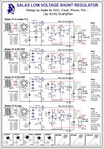
Here is the business end you need. Just use 10 leds for the shown row of 5. Feed it >7V than its output. R4 & R5 are check points for local currents that you may skip or not. We will be happy to learn about your progress and result.
Cheers
Hey Salas.
Sorry for asking a similar question yet again, but I've recently purchased the following shunt PCB from 'dvb-projekt' from this forum:
An externally hosted image should be here but it was not working when we last tested it.
An externally hosted image should be here but it was not working when we last tested it.
He said although it was designed with your 5V Shunt design in mind, it can easily be used for 24V output instead. My question would be is there another schematic of yours I can use so I can make use of this PCB for 24V output please? The schematic you kindly posted for me in post 4946 calls for 10 LEDs, but this board only has space for 3. I guess I could mount them off-board, but if there's a different schematic I could use to 'fit' this PCB for 24V I'd prefer to use that.
Many thanks Salas
- John
Last edited:
This one uses a variable resistive reference. You should use 5K Voltage Adj. trimmer instead of the 200R. Don't stuff those two 0.1u caps, give it proper input voltage, use 15R 3W Current Adj. resistor. Should fit your purposes.
Wonderful! Thanks Salas that's faberino! So leave all the values there as they already are (on the PCBs screen printing) but increase the variable resistor and leave out the pair of 0.1uF caps?
As you phrased the gist in other words correctly, yes.
Great - thank you!
An order to Mouser tomorrow and I should be good to go with this by the weekend
John
Hello Salas, i just want to know you that after i rebuilt the 1.2r from scratch and with a little different layout everything works fine, i had to put a 1k resistor before the trimmer because only 1k wasn't enough for proper setting in this configuration, i'll post some pics of my setup tomorrow
great work!
great work!
I have another quick question regarding v1.0.
Currently I'm feeding 2 LME49710HAs (used as a simple preamp) and would like to add another pair to the same reg for feeding DAC's output. It's 100uf MUSE + 1uf mks + 10nf mkp per rail now (47uf cap was replaced in accordance to preamp's scheme), do I need to add additional 47uf + bypass caps?
Also would it be enough to stay with 2200uf PS caps or they should be doubled?
Hello Salas, i just want to know you that after i rebuilt the 1.2r from scratch and with a little different layout everything works fine, i had to put a 1k resistor before the trimmer because only 1k wasn't enough for proper setting in this configuration, i'll post some pics of my setup tomorrow
great work!
Nice. Expecting pics.
I have another quick question regarding v1.0.
Currently I'm feeding 2 LME49710HAs (used as a simple preamp) and would like to add another pair to the same reg for feeding DAC's output. It's 100uf MUSE + 1uf mks + 10nf mkp per rail now (47uf cap was replaced in accordance to preamp's scheme), do I need to add additional 47uf + bypass caps?
Also would it be enough to stay with 2200uf PS caps or they should be doubled?
You mean you got those caps on the rails after the regulator's output? It may oscillate as a system with the reg. Use only 1-10uF tantalum local to the opamps +/-Vcc pins I suggest.
Stay with 2200uF, will suffice. Opamps aren't heavy draw.
You mean you got those caps on the rails after the regulator's output? It may oscillate as a system with the reg. Use only 1-10uF tantalum local to the opamps +/-Vcc pins I suggest.
Stay with 2200uF, will suffice. Opamps aren't heavy draw.
thanks, Salas!
yes, C7 47uf was replaced with the set of 100uf MUSE + 1uf mks + 10nf mkp (att.) The caps are placed on PS board then goes 10cm coax cable to preamp with no caps near +/-Vcc pins at all. Not sure though if that is a good solution...
Attachments
thanks, Salas!
yes, C7 47uf was replaced with the set of 100uf MUSE + 1uf mks + 10nf mkp (att.) The caps are placed on PS board then goes 10cm coax cable to preamp with no caps near +/-Vcc pins at all. Not sure though if that is a good solution...
Use the chip decouplers locally as the opamp circuit shows. I would simplify it to one Tantalum which has enough ESR or delete the film cap parallels to the local electrolytic, or use ceramic as Andrew said. I would restore the 47uF at reg's board. Thing is you play with decoupling and stability issues that without investigation with oscilloscope you can't know what is optimal or even basically stable for that system. Guess work involves too many layout and interaction parameters to be of any value, even theoretical.
Most are variable output. There is 1.0 1.1 1.2 1.2R & Reflektor. Which one?
Hi Salas,
I am planning to build a TP6120 based headphone amp. I will use the 'Hypno' as the entry buffer. I could use the 10V onboard regs (200mA)at the same time I think but I would prefer to push the amp with +/- 15V. I do not know what is the appropriate version for this.
Thank you for your recommandations!
- Status
- This old topic is closed. If you want to reopen this topic, contact a moderator using the "Report Post" button.
- Home
- Amplifiers
- Power Supplies
- The simplistic Salas low voltage shunt regulator