I've been working on designing a better PSU for TT motor control, but was confronted with the problem of how to accurately measure the platter speed to test the utility of the PSU. Strobe discs and the Sutherland Timeline were too awkward or inaccurate (not to mention over priced) and the handheld digital tachs don't provide enough resolution or accuracy to be useful. I decided to design a digital tach more suited to the needs of high accuracy and ease of use. Just build up the first PCBs with very good results.
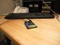
The first photo is the PCB without housing. The turntable is connected to a Music Hall Cruise Control 2.0 with 0.1 RPM adjustments. 33.266 RPM is the closest I could get the platter to track with the Cruise Control set to 33.1 RPM. This is one of the problems I noticed when working with the PSU's available out there: The speed adjust is WAY too coarse and there are too many variables that affect speed such as belt position and tension. I think my PSU will have much finer speed adjustment, something like 0.01 RPM (I can adjust the frequecy of the AC out in 1/1800 Hz steps.)
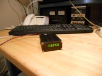
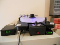
The second photo is the PCB in its housing. The third photo is the tachometer tucked under the turntable and the Cruise Control set to 33.3 RPM. Note the actual speed of the platter is 33.428 RPM which is +0.28%, not exactly impressive for a $300 PSU.
Another thing I noticed about the platter speed, is it slowly increased over time as the motor warmed up. So no matter how closely you get the speed initially by changing the belt tension (or the PSU frequency), it is due to drift over time or if you happen to change the belt location. Since the tach has a USB output for computer logging, I think it would be a natural addition to the PSU to have a USB input so the two could be synched. The mass of the platter should take care of minute changes in speed that occur within one rev and the PSU should be able to supply short term stability with a clean accurate AC signal, but the tach could correct long term accuracy by constantly monitoring the RPM and suppling a well damped feedback to the PSU and compensating for drift due to motor warming, belt tension etc.
The first photo is the PCB without housing. The turntable is connected to a Music Hall Cruise Control 2.0 with 0.1 RPM adjustments. 33.266 RPM is the closest I could get the platter to track with the Cruise Control set to 33.1 RPM. This is one of the problems I noticed when working with the PSU's available out there: The speed adjust is WAY too coarse and there are too many variables that affect speed such as belt position and tension. I think my PSU will have much finer speed adjustment, something like 0.01 RPM (I can adjust the frequecy of the AC out in 1/1800 Hz steps.)
The second photo is the PCB in its housing. The third photo is the tachometer tucked under the turntable and the Cruise Control set to 33.3 RPM. Note the actual speed of the platter is 33.428 RPM which is +0.28%, not exactly impressive for a $300 PSU.
Another thing I noticed about the platter speed, is it slowly increased over time as the motor warmed up. So no matter how closely you get the speed initially by changing the belt tension (or the PSU frequency), it is due to drift over time or if you happen to change the belt location. Since the tach has a USB output for computer logging, I think it would be a natural addition to the PSU to have a USB input so the two could be synched. The mass of the platter should take care of minute changes in speed that occur within one rev and the PSU should be able to supply short term stability with a clean accurate AC signal, but the tach could correct long term accuracy by constantly monitoring the RPM and suppling a well damped feedback to the PSU and compensating for drift due to motor warming, belt tension etc.
Attachments
VPI Motor Spike
There may be another thread that addresses this, but does anyone else have problems with the loud speaker "POP" when turning the VPI motor supply on/off? I was unable to find a solution through the mfr, distributor or on-line, so I put together a quick fix that mounts inside the motor supply and requires a minimum of rewiring.
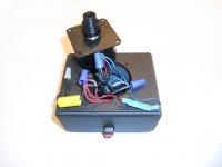
The suppressor cap across the switch (mostly useless) is removed and the wiring is done per the attached photo (the PCB is encased in the blue shrink wrap).
Before this fix, the switch would arc so badly, the protection on my Carver amp would trigger and occasionally, it would trip the arc fault circuit breakers in my electrical panel, killing power to all the equipment. With the fix in place, the speakers are totally silent when switching the motor on/off, even with my ear right in front of the speakers.
There may be another thread that addresses this, but does anyone else have problems with the loud speaker "POP" when turning the VPI motor supply on/off? I was unable to find a solution through the mfr, distributor or on-line, so I put together a quick fix that mounts inside the motor supply and requires a minimum of rewiring.
The suppressor cap across the switch (mostly useless) is removed and the wiring is done per the attached photo (the PCB is encased in the blue shrink wrap).
Before this fix, the switch would arc so badly, the protection on my Carver amp would trigger and occasionally, it would trip the arc fault circuit breakers in my electrical panel, killing power to all the equipment. With the fix in place, the speakers are totally silent when switching the motor on/off, even with my ear right in front of the speakers.
Attachments
There may be another thread that addresses this, but does anyone else have problems with the loud speaker "POP" when turning the VPI motor supply on/off?
You need a "Quench-Arc" -- it's a Mallory device (and others) -- as the switch contacts come into closer proximity your effectively bring 2 capacitor plates closer and closer. A "QA" has a resistor and capacitor which dissipate the energy.
An externally hosted image should be here but it was not working when we last tested it.
An externally hosted image should be here but it was not working when we last tested it.
Pyramid,
Are there any specs labeled on the yellow cap in the photo?
thanks,
alan
The yellow cap in the photo is the phase shift cap for the second winding. It is .5uFd 400V polypropolene I believe. I removed the 1nFd cap across the switch and installed my PCB solution (PCB is wrapped in blue shrink wrap).
The wire diagram is attached.
Attachments
I've never seen thermal drift on an AC motor controller before. Have you tried a different motor choice to eliminate that as being the variable? It might also be enlightening to use a much heavier weight oil in the TT bearing so that viscous drag swamps any slight variation in load from the needle.
I run a Kuzma deck with silicon diff oil in the bearing and it gives rock solid speed stability due to the added drag swamping cogging effects.
Might be worth a try...
I run a Kuzma deck with silicon diff oil in the bearing and it gives rock solid speed stability due to the added drag swamping cogging effects.
Might be worth a try...
I suppose it's possible if it uses an "analog" oscillator rather than a digitally-based output derived from a crystal oscillator.I've never seen thermal drift on an AC motor controller before.
Likewise, the motor itself is almost surely synchronous, and should never "lose" a cycle unless the voltage into it is marginal, or an excessively distorted sine wave.
To convince yourself of this, you could use the device tracking the platter speed on the motor pully, and satisfy yourself that its speed doesn't change over time.
I can see where this could help, though one of my thoughts as to why it speeds up longterm is that the bearing and oil warm up slightly, thus the oil has lower viscosity and is easier to turn. Likewise the belt "loosening up" or warming up in operation could have an effect. From the description, changing belt tension definitely affects the speed, and it's reasonable to think that as the belt operates and wears, its length and thus tension changes on its own.Have you tried a different motor choice to eliminate that as being the variable? It might also be enlightening to use a much heavier weight oil in the TT bearing so that viscous drag swamps any slight variation in load from the needle.
And to me this points to using a different or better belt.
VPI Scout speed control
I don't think it is the controller that is drifting, although the Music Hall Cruise control uses an uncompensated xtal with a stability of ~100-200PPM, not the 1PPM they publish. Some of the other posters may have identified other possible causes of drift besides the motor itself, I really didn't investigate it further. Regardless of the source, it exists and needs to be dealt with. It is one of the phenomena that I noticed since I started researching TT speed control: People (and even the magazines who review products) seem to take published specs at face value without verifying the data. One of the reasons I built the tach was to do just that--accurately measure the results of any tweaks or commercially available "solutions" that I might apply. Many of the end user reviews of PSU's revolve around the improved sound, very little about how accurately they control the speed though.
I've never seen thermal drift on an AC motor controller before. Have you tried a different motor choice to eliminate that as being the variable? It might also be enlightening to use a much heavier weight oil in the TT bearing so that viscous drag swamps any slight variation in load from the needle.
I run a Kuzma deck with silicon diff oil in the bearing and it gives rock solid speed stability due to the added drag swamping cogging effects.
Might be worth a try...
I don't think it is the controller that is drifting, although the Music Hall Cruise control uses an uncompensated xtal with a stability of ~100-200PPM, not the 1PPM they publish. Some of the other posters may have identified other possible causes of drift besides the motor itself, I really didn't investigate it further. Regardless of the source, it exists and needs to be dealt with. It is one of the phenomena that I noticed since I started researching TT speed control: People (and even the magazines who review products) seem to take published specs at face value without verifying the data. One of the reasons I built the tach was to do just that--accurately measure the results of any tweaks or commercially available "solutions" that I might apply. Many of the end user reviews of PSU's revolve around the improved sound, very little about how accurately they control the speed though.
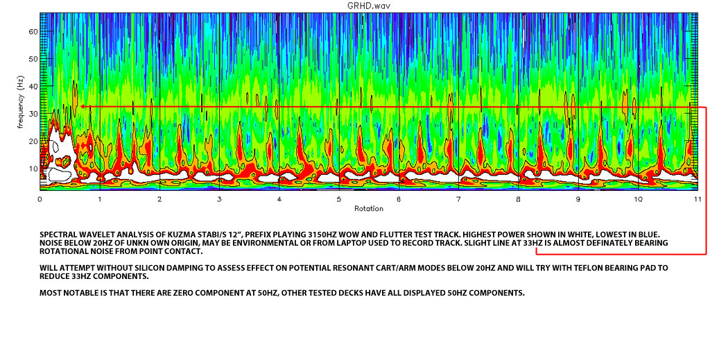
You should check out the ' turntable speed stability' thread in the DIY section of pinkfishmedia there's plenty of info and measurement on there, including some funky wavelet analysis and some FM demodulation of samples recorded with 3500hz test tones.
Do you have a way of checking to make sure the tacho gives an accurate reading and that it isn't the course of the apparent drift?
Do you have a way of checking to make sure the tacho gives an accurate reading and that it isn't the course of the apparent drift?
VPI Tachometer
In order to get .001 RPM resolution requires the ability to resolove precession or recession of the platter rotation within 0.628 MILs per rev.
The tach triggers once per rev and the stability of that trigger point is very important for accuracy (the clock is xtal controlled using a temp comp TCXO with trimmer for absolute accuracy). The trigger width is 10's of mS, so the uP outputs a shorter pulse (300uS) that I use to fire a high brightness LED to use as a strobe. I have a 40 AWG wire at a fixed position and a piece of a machinists scale taped to the top of the platter; the strobe fires when the scale passes below the wire pointer. Examining it under an Edmund stereo microscope, I can not detect any ambiguity in the trigger point, so the reading should be correct within at least one count. The bobble of the last digit can be a bit distracting (if not concerning), so one of the solder jumpers on the PCB blanks the last digit and produces a more pleasing (stable) display. I can always unblank the last digit for more precise measurements, but the effect of a stable display has some merit.
Using a tone from a disc is an easy way to measure rotational accuracy, but with a 3kHz tone, you need to be accurate to ±0.1 Hz which can require a long gate period. If you measure the frequency across several revs, you loose important information about stability as the reading will be averaged.
I'm using 30K counts/Sec to acheive that accuracy and you can use the tach while listening to music.
You should check out the ' turntable speed stability' thread in the DIY section of pinkfishmedia there's plenty of info and measurement on there, including some funky wavelet analysis and some FM demodulation of samples recorded with 3500hz test tones.
Do you have a way of checking to make sure the tacho gives an accurate reading and that it isn't the course of the apparent drift?
In order to get .001 RPM resolution requires the ability to resolove precession or recession of the platter rotation within 0.628 MILs per rev.
The tach triggers once per rev and the stability of that trigger point is very important for accuracy (the clock is xtal controlled using a temp comp TCXO with trimmer for absolute accuracy). The trigger width is 10's of mS, so the uP outputs a shorter pulse (300uS) that I use to fire a high brightness LED to use as a strobe. I have a 40 AWG wire at a fixed position and a piece of a machinists scale taped to the top of the platter; the strobe fires when the scale passes below the wire pointer. Examining it under an Edmund stereo microscope, I can not detect any ambiguity in the trigger point, so the reading should be correct within at least one count. The bobble of the last digit can be a bit distracting (if not concerning), so one of the solder jumpers on the PCB blanks the last digit and produces a more pleasing (stable) display. I can always unblank the last digit for more precise measurements, but the effect of a stable display has some merit.
Using a tone from a disc is an easy way to measure rotational accuracy, but with a 3kHz tone, you need to be accurate to ±0.1 Hz which can require a long gate period. If you measure the frequency across several revs, you loose important information about stability as the reading will be averaged.
I'm using 30K counts/Sec to acheive that accuracy and you can use the tach while listening to music.
You can get encoders with far more than one pulse per revolution. Not sure if that might help you with the issue of timing for this application or not. I'm guessing that integrating 100 pulses would be pretty darn accurate even with a minor degree of offsets...
The other question is why does anyone *need* 0.001RPM resolution, since one never knows precisely what the speed of the lathe, the tape machines etc were?? Speed stability is not the same as measurement resolution, and it's stability at an appropriate speed that counts most. Unless ur trying to correct an offspeed disc, then it's by ear I would expect anyhow?
_-_-
Last edited:
You can get encoders with far more than one pulse per revolution. Not sure if that might help you with the issue of timing for this application or not. I'm guessing that integrating 100 pulses would be pretty darn accurate even with a minor degree of offsets...
The other question is why does anyone *need* 0.001RPM resolution, since one never knows precisely what the speed of the lathe, the tape machines etc were?? Speed stability is not the same as measurement resolution, and it's stability at an appropriate speed that counts most. Unless ur trying to correct an offspeed disc, then it's by ear I would expect anyhow?
_-_-
There are encoders that produce 3K+ pulses/Rev, but they are geared and anything that contacts the platter has the potential to slow it down, especially when you are measuring rotational velocity to 3 decimal places. 100 pulses/rev would not give you the accurcay needed. The tach accumlates 54,000 clock counts/Rev at 33 1/3 RPM. 54,001= 33.33271; 53,999=33.33395 RPM.
As I stated in my previous posts, I built the tach because there wasn't anything available to ACCURATELY measure platter speed. Stobes and the Sutherland Timeline are only indicators and not very good ones at that (and not practical when listening to music). I don't think that measurement instruments can be "too" accurate. In fact, the more accurate they are, the better they can be used as tools to verify the operation of sometimes expensive tweaks. If the goal is to produce stable and accurate platter speeds, the better the tool, the better the results.
As far as sonic quality, it takes ~±0.44% error to change a note to flat or sharp, but the ear can detect errors less than that. You are correct that stability is at least important as absolute accuracy, but the goal should be both. The mass of the platter should mitigate any minute changes in speed (<1 rev). An ACCURATE PSU should provide short term stability, but even the best designed power supply will exhibit platter speed drift over time for any of the variables identified in previous posts. The tach should provide the last piece of the puzzle by providing long term accuracy by monitoring and synching the PSU.
If speed and stability are not an issue, there is an entire industry devoted to nothing worthwhile.
As far as sonic quality, it takes ~±0.44% error to change a note to flat or sharp, but the ear can detect errors less than that.
What does that mean?
Sorry, I did the math based on 16 equal half steps per octave, not 12 (and the decimal is off by one). 12 equal steps equals a frequency difference of ~ 5.95% between half notes. So TT platter speed needs to be quite large to cause "flat" notes, but most listeners can detect off speed playback at a lower threshold than that.
Pyramid, Excuse me if I'm getting this wrong, but you have one mark on the underside of the platter, correct?
If that's the case than 'anything' can be happening between the mark passing on one revolution and the next. You can slice that revolution up into as many chunks as you like, the measured resolution accuracy of your set-up remains the same. Theoretical accuracy goes up, but with only one true reference to position per revolution the actual resolution remains the same.
Put succinctly, you know where your platter is once per revolution, and only once per revolution, interpolation between this point and the next rev is purely guesswork. Apologies if I have misunderstood your trigger mechanism.
*The point being is that your set-up tells you very accurately how much too fast you are or too slow you are 'per' revolution, but tells you nothing about what's going on between these sample points. You could have a lot of very high frequency speed perturbations per revolution, or you could have a very smooth change. The difference between knowing which is huge.
Here's two measurements of the same test record that give you a lot of info.
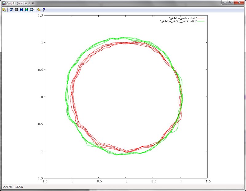
The first is an FM demodulation of the 3.5khz sample tone. Any deviation from a perfect circle is a deviation from 3500hz. The resolution is high >0.1 degree. (There are two samples shown, one using the nominal 0.22uf phase shift capacitor as recommended by the motor maker and the other using a hand trimmed value that is better suited to the actual- rathe rthan nominal, motor specification).
Both of these teach you far more about your set-up than simply how many gazillionths of a second fast you are each revolution. ;-)
If that's the case than 'anything' can be happening between the mark passing on one revolution and the next. You can slice that revolution up into as many chunks as you like, the measured resolution accuracy of your set-up remains the same. Theoretical accuracy goes up, but with only one true reference to position per revolution the actual resolution remains the same.
Put succinctly, you know where your platter is once per revolution, and only once per revolution, interpolation between this point and the next rev is purely guesswork. Apologies if I have misunderstood your trigger mechanism.
*The point being is that your set-up tells you very accurately how much too fast you are or too slow you are 'per' revolution, but tells you nothing about what's going on between these sample points. You could have a lot of very high frequency speed perturbations per revolution, or you could have a very smooth change. The difference between knowing which is huge.
Here's two measurements of the same test record that give you a lot of info.
The first is an FM demodulation of the 3.5khz sample tone. Any deviation from a perfect circle is a deviation from 3500hz. The resolution is high >0.1 degree. (There are two samples shown, one using the nominal 0.22uf phase shift capacitor as recommended by the motor maker and the other using a hand trimmed value that is better suited to the actual- rathe rthan nominal, motor specification).
Both of these teach you far more about your set-up than simply how many gazillionths of a second fast you are each revolution. ;-)
Last edited:
Turntable speed measurement
sq225917- Very good explanation of what is happening. You are correct that I am only measuring rotational velocity based on a once/rev position. That was my goal: to determine with some accuracy the platter speed on a longer time scale. What you are describing is more of speed stability (which as we all seem to agree, is also important). Controlling the speed on a sub-rev basis would be nearly impossible on a belt drive system given the elasticity of the drive mechanism and the inertia of the platter. I think the best way to control short term stability is by using the inertia of the platter to prevent small variations within a single rev. An accurate PSU should provide longer term stability, but can't anticpate drift due to bearing/motor/belt changes that occur over time. Accurate monitoring of the speed that is fed back to the PSU should prevent the long term "drift" that the PSU can't anticipate or prevent.
FYI, I'm using a mirrored surface on the outside edge of the platter with an LED emitter/detector pair as the sensor. This is not a very elegant solution to triggering and am looking at optical imaging sensor technology commonly used in optical mouse applications as an alternative. That would allow contactless sensing and would give stability information per rev, but again, I'm not sure what you could do with that shorter term info given the belt drive mechanism.
Your analysis tool does a very good job when focusing on a specific criteria. Different tasks, different tools.
Pyramid, Now I understand, you're looking at longer term drift.
So far the best method to minimize short term instability that I've seen and tried is by loading the bearing with a thicker oil (silicon oil in my case) so that viscous drag from the bearing becomes so large that it swamps all other causes of variance, (or at least additive ones). As mentioned earlier it also all but eliminates cogging effects, usually caused by the motor being under virtually no load in a free running deck with a high mass and low drag bearing.
Of course at the end of day anything that uses a test record to define a measurement of speed stability is only as good as the pressing. A friend has tried using an optical sensor with a printed media placed under the platter, he quickly ran into issues with resolution. I hope you fair better with the mouse solution- that sounds like it should have legs (excuse the pun).
Turntable speed control
sq225917- The software you showed might be handy for adjusting the PSU phase angle. I anticipate 3 versions of the PSU, one of them with two line voltage outputs intially at 90° phase difference, but adjustable to get the lowest vibration. I also had thoughts of altering the phase at motor start up to maximize torque as well.
I went to pinkfishmedia(dot)com, but I couldn't find the thread you were talking about. It seemed to be a site devoted to advertising other websites. Do you have info on the software/test disk?
Pyramid, if half the time ur platter was fast by "N" and half the time it was slow by "N" and what you are doing is integrating (averaging over time) "X" samples of single points on the revolution, you would still apparently find speed stability, but you would not have any.
I'm not sure how your approach shows you long term drift??
It would if the drift was unidirectional over some period of time that corresponded to the sample window's averaging.
I'm maybe just confused as to how it works...
As far as encoders, dunno about geared encoders, but from what I have seen there are direct optical encoders that will do incredible accuracy. Maybe the highest resolutions, down into angstroms require software deconvolution to read, but somewhere between there and one tick per revolution is a good place to end up?
_-_-
VPI turntable speed
It works just like every other tachometer does. Does the tach on your car engine tell you the number or magnitude of small pertubations in the engine's speed?
What do you consider "incredible" accuracy? Do you have any specs or model numbers I could look up? Are they contact type encoders? I tried to stay away from anything that would affect the speed through contact and most of these encoders would make monitoring the speed during disc play impossible or impractical.
I'm maybe just confused as to how it works...
It works just like every other tachometer does. Does the tach on your car engine tell you the number or magnitude of small pertubations in the engine's speed?
As far as encoders, dunno about geared encoders, but from what I have seen there are direct optical encoders that will do incredible accuracy. _-_-
What do you consider "incredible" accuracy? Do you have any specs or model numbers I could look up? Are they contact type encoders? I tried to stay away from anything that would affect the speed through contact and most of these encoders would make monitoring the speed during disc play impossible or impractical.
- Home
- Source & Line
- Analogue Source
- The Official Turntable Drive System/Motor Thread!