Any heat problems from R1 and R4 being so close together, and so near to PS cap?
Andrew, please elaborate for us non-techs. You're saying break the PCB path around the PGND connection of the smoothing caps, then hardwire both negative cap pins to the PGND connection coming from the transformer? What then connects audio ground? Would that be a parallel connection back to the transformer from the existing connection point?
Does R11 have anything to do with isolating power ground from audio ground?
Peace,
Tom E
Hi Madison,
I assume you are asking about my comment that this grounding mod can be implemented on the v1.2 PCB.
The Zero Volt pins of the two smoothing caps are connected to each other on the top side. Along this long & wide copper trace are various ground connections for all the other PCB services and there is a connection back to the AC centre tap.
The AC centre tap and the two AC connections come in via a three wire twisted triplet.
The spade labeled PGND is too closely linked to the wire PTH on the top side. Leave this spade connection on the top side.
The two capacitor Zero Volts pins connection via 4mm wide traces. These traces can be cut to leave the caps isolated from the Audio Ground.
Now hard wire the Zero Volts pins on the bottom side to the big PTH labeled PGND.
The capacitor to rectifier currents will pass through the hardwiring on the bottom side.
The audio currents will run into and out of the remaining Star Ground on the top side.
The PTH connects bottom side to top side.
This PTH needs to be filled with copper wire. solid core or stranded will do but try to fill it before soldering the PTH at top and bottom sides.
Post1018 refers to the v1.3pcb. That should have read v1.2pcb
Last edited:
I see that Mauro has a lot of capacitance on the Evolution in the power supply. What do you/you all think about having at least 4x10,000uf on each board?
Uriah, pay attention to the fact that the Evolution has two current pumps per channell, it's for those that 4 big caps are provided.
Ok, so here is where it departs from Mauro's design and evolves to a new one "based" on his contributions.
I would explore first LM318's PS... and a DC servo to replace C9, like in the REAL Evolution.
")
...Uriah, pay attention to the fact that the Evolution has two current pumps per channell, it's for those that 4 big caps are provided.....
But it was mentioned that it sounded better with a single 3886 chip...
But it was mentioned that it sounded better with a single 3886 chip...
I can't remember this detail but for sure in case of a single 3886 only two caps per channel should be mounted...
I would like to see the PSU Zero Volts separated from the main Audio Star Ground.
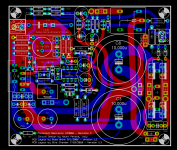
OK, here's the change to implement that, and also an additional spade connector for PGND which is (hopefully) more accessible. The trace width to the second PGND isn't as wide as I'd like, but there isn't sufficient isolation from other nearby traces to be able to accommodate a thicker trace. An additional wire can be soldered in parallel with the trace from PGND to PGND1 if this is a concern.
The Audio star ground isn't as optimal as I'd like, but it's the best that can be done to allow it to coincide closely with the large PGND PTH. Feel free to post any ideas to improve this, though it may not make it to this version.
Edit: A couple of airwires of the audio ground to PGND net are unrouted. Eagle doesn't seem to understand that the big PTH connects the Audio ground to PGND, i.e. that is electrically equivalent to a Via. It wants an explicit via to be inserted while routing that airwire.
Attachments
Last edited:
Any heat problems from R1 and R4 being so close together, and so near to PS cap?
Even at +/- 35V rails (higher than the recommended +/- 32V), the dissipation in each resistor is only 23*23/1k = 0.529 W. The 1W resistors originally specified are perfectly adequate, and 2W gives a huge margin of safety. The combined dissipation in R1 and R4 of ~1W is not a concern - consider that most modern PC processors dissipate 65W to 130W, and the VRM MOSFETs for these often don't have heat-sinks and are in close proximity to small electrolytics.
The 1W resistors originally specified are perfectly adequate, and 2W gives a huge margin of safety.
Nevertheless they're damn hot!
I would give them more 'air'
I see that Mauro has a lot of capacitance on the Evolution in the power supply. What do you/you all think about having at least 4x10,000uf on each board?
IMHO, the topology inherently has high PSRR because of the LM318, and you probably won't need anything higher than 10,000 to 12,000 uF to reduce the AC ripple. However, there's no harm in experimenting with larger valued caps.
With the 35mm outlines on Version 1.3, you can comfortably fit the 18,000uf or 22,000uF, 50V Panasonic TS-UP and manage with just 2 caps.
For the 4-capacitor configuration (a la Evolution), the placement of the main caps will be better just below C1 and C2, i.e. the form-factor of the PCB will have to change significantly. That's best pushed out to a future (1.4?) version - which could also have paralleled current pumps using two LM3886s or one LM4780 per channel.
Last edited:
Nevertheless they're damn hot!
I would give them more 'air'
The alternative is to dump the shunt regulator (R1, R4, ZD1, ZD2) and switch to 3-terminal regulators - I'll put this on the wish-list for version 1.4 (anything which involves a material change to the RevC topology probably won't get included in version 1.3).
I'd suggest that the 1.x be reserved exclusively for identical topology to the original Mauro Penasa design as implemented by Russ.anything which involves a material change to the RevC topology probably won't get included in version 1.3
Changes to the topology could use 2.y as a reference provided the PCB makes that change from Mauro's design clear.
The alternative is to dump the shunt regulator (R1, R4, ZD1, ZD2) and switch to 3-terminal regulators
I wasn't suggesting nothing so extreme, just to move a bit R1 and R4 so that there's more space between them..
BTW Mauro tried also 3 terminal regulators and he preferred the Zeners...
For a next revision I would try something like TL431 or simply zener + transistor...
Like this one from ESP site:
An externally hosted image should be here but it was not working when we last tested it.
I'd suggest that the 1.x be reserved exclusively for identical topology to the original Mauro Penasa design as implemented by Russ.
Changes to the topology could use 2.y as a reference provided the PCB makes that change from Mauro's design clear.
Makes good sense and shows a respect for Mauro and TPA's design and layout.
Linuxguru, True, I could use just larger caps since you have made provision for such on the board.
Uriah
Changes to the topology could use 2.y as a reference provided the PCB makes that change from Mauro's design clear.
Yes, seconded - it allows development on both branches separately.
- Home
- Amplifiers
- Chip Amps
- The new "My Ref" Rev C thread