What about adding a trace and pads for a CL60 to connect PS ground to safety ground?
Is it preferred to isolate each PS ground (i.e. for each board) from safety ground separately? I would have thought that all the power supply grounds were tied together, and connected to safety ground through one isolator - which would suggest an off-board location for the CL60.
I would definitly remove the old monolythic diode bridge.
It's not a bad idea to place the CL60 onboard. If you use one per each more, you will reach a higher level of isolation between each grounds. You can label the board as an optional position, leaving the option to not use it.
Place one CL60 from the center (or near) of the star ground and connect it to protective earth of the IEC socket or chassis. Then do the same with the other amp.
Regards,
Regi
Late arrival here. Is the My Ref C kit or PCB still available anywhere? If not as a kit, where's the proper (final) BoM? Thanks.
You can buy PCBs on Uriah's site: BuildYourAmplifier.
Attached:
MyRefC - The official Uriah's BOM (no codes)
My_Ref Ultimate Rev C BOM stable - The (unofficial) BOM that I've prepared for PCBs only buyers
My version is as similar as possible but its goal is to be easily ordered from Mouser and Digikey (both suppliers required). Some notes inside.
Attachments
Meanwhile, keep the suggestions coming, I'll try to incorporate the high-priority ones before freezing the layout at the middle of this week.
Hi again LinuxGuru,
my friend Marco asked me to suggests to move C3, C8 near C1, C2, like in Mauro's Evolution.
I have no idea if it's better...

Attachments
...suggests to move C3, C8 near C1, C2, like in Mauro's Evolution.
I thought about that, but it's definitely for a future version. The track length for the power rails shortens considerably, but it also changes the form factor completely with the long axis of the PCB parallel to the heatsink. It probably works well for a back-to-back stereo board like the Evolution. It's worth looking into for a future stereo version of the RevC.
I would definitly remove the old monolythic diode bridge.
...
Place one CL60 from the center (or near) of the star ground and connect it to protective earth of the IEC socket or chassis. Then do the same with the other amp.
I'm retaining the bridge rectifier for the benefit of those using a Value BoM, where the price of the bridge rectifier is as low as a single MUR820 - an important consideration in some regions.
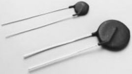
Could you post a picture of the CL60 and/or provide the dimensions and pad size, etc.? Will a vertical resistor decal from Eagle's RCL library suffice? There's space for this near the lower right corner, but if it's too large, I'll probably leave it out in this version.
Must the CL60 be connected directly at the star ground, or just on the ground trace? It might fit at the edge of the board, between and below R1 and R4. It's nice to have the wire at the edge of the board.
Peace,
Tom E
Rough drawing but it shows the idea...
Attachments
Rough drawing but it shows the idea...
That's where I put it tentatively, too; including the copper extension to the mounting hole. However, I could not find a matching decal in Eagle's libraries, including varistors/thermistors, etc. for a 0.328" (~8 mm) pitch device. Is it ok if I put in a generic 7.5 mm varistor decal, or is it too tight?
What about placing it under R1 and R4, as Tom proposed? There's enough clearance out there.
Using the mounting hole for grounding purposes seems like a practical approach, but that way you will be forcing people to use, well, the mounting hole as a grounding method.
Anyway, I am making a mess of my mind, both solutions are appropiated. Nevermind, just talking for talking
Regards,
Regi
Using the mounting hole for grounding purposes seems like a practical approach, but that way you will be forcing people to use, well, the mounting hole as a grounding method.
Anyway, I am making a mess of my mind, both solutions are appropiated. Nevermind, just talking for talking
Regards,
Regi
...Using the mounting hole for grounding purposes seems like a practical approach, but that way you will be forcing people to use, well, the mounting hole as a grounding method.
.....
Regards,
Regi
I meant to put another pad there so you could jumper it to the mounting hole or use a wire to the chassis grnd.
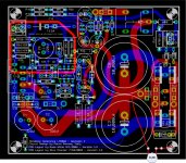
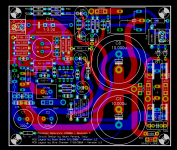
Here's the current state of the layout, still work in progress. Things left to do:
1)The small caps have to be updated for larger circular pads and dual 5mm-7.5 mm decals.
2) Some placement may have to be fine-tuned. C21 placement still not resolved.
3) Some fonts and text placement to be adjusted.
4) Drills for small resistors to be up-sized one step.
5) CL60 decal, placement and routing is tentative - may still be removed if unsatisfactory.
Layout freeze may be pushed back to the weekend, if necessary.
Attachments
Last edited:
Here's the current state of the layout, still work in progress.
I would suggest to:
- remove the connection between the mounting hole and safety ground. Your solution is already elegant.
- make the connection between PGND and CL60 thicker.
- Revise the Zeners and associated resistors, the original was way more elegant.
- In any case remove the ground connection between C6 and C11 and replace it with a connection betweeen C6 and the star ground
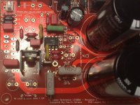
- Space around R3 is still not enough... (see photo)
Attachments
Well, I think now that the CL60 fits there like a glove. Now I like it
But still, unavoidable tied to the standoff.
Does somebody knows if the distance from the zener to the IC affects its performance in anyway? I know what happens with regulators, but never worked with zeners before.
If so, the seem to be closer now, so it COULD work better.
I would turn C11 90 degrees counterclockwise, so it will be closer to C7 and the zenner. The other leg of C11 goes to ground, so is not so important to keep it short.
I can see an slim red trace going from R13 resistor's leg to R9's leg, and then it continues. What's that supossed to be?
We are heading to a very nice optimization for this PCB, keet it going!
Well, I think now that the CL60 fits there like a glove. Now I like it
But still, unavoidable tied to the standoff.
Does somebody knows if the distance from the zener to the IC affects its performance in anyway? I know what happens with regulators, but never worked with zeners before.
If so, the seem to be closer now, so it COULD work better.
I would turn C11 90 degrees counterclockwise, so it will be closer to C7 and the zenner. The other leg of C11 goes to ground, so is not so important to keep it short.
I can see an slim red trace going from R13 resistor's leg to R9's leg, and then it continues. What's that supossed to be?
We are heading to a very nice optimization for this PCB, keet it going!
The CL60 does not have to be tied to the standoff if enough holes are provided to program that connection with a jumper wire. Still the connection to the standoff is quite convenient and most builders would probably use it.
Zeners are rather high impedance compared to regulator IC's so I don't expect the placement to be ultra-critical. C11 and C7 appear to be optimally placed and I would not recommend your suggested changes. C7 should be connected with shortest traces to the LM318. Next shortest traces to the LM318 should be C11. Ground and supply traces add equally to degrade the effective impedance of C11 so both must be considered carefully.
The trace from R13 to R9 indicates connections that are part of a copper shape or mini-plane if you prefer. This was part of version 1.2 as well.
I can see an slim red trace going from R13 resistor's leg to R9's leg, and then it continues. What's that supossed to be?
It's a zero-width trace to ground, to keep Eagle happy that all signal traces are routed. However, it seems unneccessary - if you hit the 'rat's nest' button, Eagle optimizes these out if they are airwires. I've removed some of those zero-width traces now, will try to remove all extraneous ones (many are buried inside thicker traces) before extracting the Gerbers.
The CL60 does not have to be tied to the standoff if enough holes are provided to program that connection with a jumper wire. Still the connection to the standoff is quite convenient and most builders would probably use it.
I've now removed the copper trace from the connector (below the CL60) to the standoff/mount hole. It's now an option to the builder whether to jumper it to the standoff or to use a lug-connector or similar, from the safety-ground connector to the chassis, where it may be terminated (star-connected) at a single point.
I'll try to provide an additional pad to make this jumpering easier.
One concern that has occurred to me is that there are now several pads (including the safety-ground connector and one row of the LM3886 chipamp) that are very close to the edge of the PCB, and may cause the PCB to fracture near the edge if unduly stressed.
Last edited:
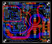
Here is the current layout - not many visible updates today. I've made C4, C5 and C21 into multi-pitch 5, 7.5 or 10 mm outlines. Next on the agenda is to make C7 (and maybe a few others) a 2.5/5/7.5 mm multi-pitch outline. Then some minor clean-up near C6/C11 and the zeners. Some drill and pad size fixes, and it should be good to go - maybe by the end of the week.
The R3 heatsink issue is messy - maybe the best option is to use a high-mounted heatsink without the lower fins, which should allow it to comfortably clear the components around it.
The R3 heatsink issue is messy - maybe the best option is to use a high-mounted heatsink without the lower fins, which should allow it to comfortably clear the components around it.
Attachments
Last edited:
- Home
- Amplifiers
- Chip Amps
- The new "My Ref" Rev C thread