Thanks for the links Stuart.
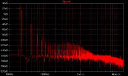
Homemodder, how do you like this? 60V pk-pk into 8 ohms, 68db GNFB. Perhaps with some more mods...
The output bias setting will largely factor in to the harmonic profile. I still don't know exactly how I should choose a bias setting. Slightly overbiasing decreases ultrasonic trash at the expense of H7 and co. "correct" biasing the way I figure it, decreases H7 and thereabouts at the expense of ultrasonics.
- keantoken
Thats a high feedback design, I have nothing against feedback can work very well although I prefer to have OL bandwith at least over 5Khz . Just looking at that plot tells me it is most probably a triple outputstage. Which amp is that from, the cyrus 1 ??? Those amps sound very good.
Careful homemodder I think I'm gaining ground. ")
That amp is one I designed myself, that is beginning to look so good I will simply have to build it. The output stage is a triple sort of, but with the same voltage swing of a double.
I changed compensation at the expense of low order harmonics, but everything above 5th harmonic is below 100db.
How does your amp perform into 10n and 100n loads?
Ostripper - try referencing Cdom (C6 in your schematic) to the output instead of the VAS output. It will be harder to get stable but I think you will see less high order stuff. If you can't get it stable add a 500p cap from VAS output to ground and see if that helps.
- keantoken
Attachments
............
try referencing Cdom (C6 in your schematic) to the output instead of the VAS output. It will be harder to get stable but I think you will see less high order stuff. If you can't get it stable add a 500p cap from VAS output to ground and see if that helps.
- keantoken
E.M. Cherry did just that, though it's asking for trouble. Instead, try TMC.
Cheers,
E.
It looks like a typical LTP vas profile amp, Ive stopped designing them some years ago, I prefer fast amps with slew rates in access of 100v/us.
That could only be a cfp driver ef, they very good too especially if you use ccs s on drivers, I used this on a amp back in 1996, a favourite of Harmon Kardon.
Build it, it should sound fine, distortion is low and the profile is good.
Do you mean with those caps accross the load or without any load on the output ?? The amp is stable running speakers to full output without a coil, theres no problem in the sim either, with a coil I can however put a 5uf cap accross the load and it is still stable.
Tmc
It's an alternative for two pole compensation (TMC = Transitional Miller Compensation).
The discussion about this topic started here: http://www.diyaudio.com/forums/soli...terview-negative-feedback-45.html#post1157914
edit: Or here: http://www.diyaudio.com/forums/soli...terview-negative-feedback-47.html#post1158797
Cheers,
E.
I've heard of two pole compensation, but what is TMC?
- keantoken
It's an alternative for two pole compensation (TMC = Transitional Miller Compensation).
The discussion about this topic started here: http://www.diyaudio.com/forums/soli...terview-negative-feedback-45.html#post1157914
edit: Or here: http://www.diyaudio.com/forums/soli...terview-negative-feedback-47.html#post1158797
Cheers,
E.
Last edited:
It looks like a typical LTP vas profile amp, Ive stopped designing them some years ago, I prefer fast amps with slew rates in access of 100v/us.
That could only be a cfp driver ef, they very good too especially if you use ccs s on drivers, I used this on a amp back in 1996, a favourite of Harmon Kardon.
Noop, try again!
Build it, it should sound fine, distortion is low and the profile is good.
Do you mean with those caps accross the load or without any load on the output ?? The amp is stable running speakers to full output without a coil, theres no problem in the sim either, with a coil I can however put a 5uf cap accross the load and it is still stable.
Most high-OLG amps, like linear power supplies, have a "dead zone" around 10n-100n across the load, but then will be fine with say 1uF. My amp is stable into 1uF without an output coil, but at least with the new compensation won't tolerate 10-100n.
It's an alternative for two pole compensation (TMC = Transitional Miller Compensation).
The discussion about this topic started here: http://www.diyaudio.com/forums/soli...terview-negative-feedback-45.html#post1157914
edit: Or here: http://www.diyaudio.com/forums/soli...terview-negative-feedback-47.html#post1158797
Cheers,
E.
Fascinating! I need to rig up a neural network to to plow through those Cordell and blowtorch threads and scoop up all these arbitrary conversations. I find Andy_C's two pole transitional miller compensation fascinating as well.
(that's TPTMC!)My aim in bypassing the OPS completely is to quarantine crossover distortion from being injected capacitively. In simulation, the OPS input current doesn't contain nearly as much trash as it's input voltage so if you can manage to keep capacitors away from the VAS output usually any increase in THD is of low order distortions.
- keantoken
...
Fascinating! I need to rig up a neural network to to plow through those Cordell and blowtorch threads and scoop up all these arbitrary conversations. I find Andy_C's two pole transitional miller compensation fascinating as well.
...
- keantoken
Two pole TMC is not quite achievable.

Thank you , kean. I now know more.
Wow , this amp has ridiculous low 5th and 7th) Too bad everyone is too stuckup to build this amp. They would rather build schoolboy 30 year old designs and discuss blackgate caps and other esoteric B_S.
A shame , it is still simple , 25 components and a cheap $9 OPS (njw0281/0302) which can overwhelm any speaker out there.
Edit : 20k is impressive , too ... for a simple amp.
OS
Whats so great or better about it, vs the 30 yr old designs ?
Isn't the output stage a bit weak for 200 w @ 8 ?
by E stuart - (TMC = Transitional Miller Compensation).
VERY interesting , I did get it to work with the mongrel. This also led me to drop the "center cascode" and use just 1 Cdom with the VAS (as it should be).
I did the series equation to pick my Cdom caps (stuarts were close) , stepped the feedback resistor value from 1 - 10k to see bode plot changes. On my second sim , I tried to see if lower distortion could be achieved ... nope , BUT at very high power levels (120v p/p) , I did get better THD and lower odd harmonics.
At NO TIME was there any instability with BJT's like was mentioned in the thread. The improvements were slightly better performance and stability at high power and freq.
OS
By a. wayne Whats so great or better about it, vs the 30 yr old designs ?
I should of said 50 year old designs. Most of the class B amp designs at DIYA are sad attempts at retro ( I speak of the top 3 with 500k views). By descending view at DIYA - solid state, they are 3 , 5 , and 6. I will mention and praise # 3 (symasym) , it is the only audiophile offering , but very small and it IS the 30 year old design.
5 and 6 are just hacks of the 50 year old designs - I built them , gave em' to the kids to use with their PC's. I asked questions about these amps , got very few answers "did not know what the compensation on LTP did" (5). #6 won't /can't answer any questions at all about how any of his amps work !!!! what B__s ... can I use a fast fairchild part ...."NO!" is the answer.
So 5 and 6 are "stuck" ,at least as instruments of learning and using 20-30 year old parts (mje340/50 , BD/BCxxx). The supersym and mongrel at least have much lower distortion , use 2-5 year parts (KSA/C <NJW ops's) and with just a little more complexity , are super stable and designed to last.
In the USA , I would be scared to build and sell amps 5 and 6 for legal concerns. Also , you can get better design of 5 and 6 from china , WITH modern parts. (The chinese troll this site for product ideas).
As far as the OPS... with 3 pairs NJW0281 at 2A SOA / 70V x 3 = 6a = easily 200w. In the real world with 4 devices I run 250w EASY - ALL DAY , even plugged it in to a oven coil (7 ohms).
OS
Last edited:
Kean try the amp that Os first built, I cannot recall its name now but its a commercial one, Os can help here, it was in a thread of his and maybe he still has the lt files. I battled to get it stable and when it was, it was far off the commercial unit and had many extra parts.
OS, was your high power Symassym unstable? Which amp is homemodder referring to?
OS, was your high power Symassym unstable? Which amp is homemodder referring to?
Probably the frugalamp series , they were those "50 year old designs" (RCA/SELF based). When I became smarter , I fixed them and gave them to the kids.
The supersyms I still have. I would keep them but they are "DIY style" ... they sound real good
. I want commercial looking , overbuilt lab grade amps but with the "supersym" at the core. (toner transfer all the way- no sharpie)That is the reason for the 'mongrel" ...A supersym/symasym wrapped in every economical enhancement this site has to offer while still keeping it fairly simple.
My goal is to have the complexity somewhere between a quasi amp and one of the advanced PPM amps (syn08 stuff) , the build to be as easy as a quasi or symasym (perhaps easier).
I am down to 24 transistors (4 dual smd's, 8 to-126 , 2 to-220 , 6 OPS) .. just 15 US dollars and no matching. Cheap for .001% at 100watts - 20k

OS
I am trying a PCB for your symasym in two parts, voltage and output stage separate. That way it would also be easy to try the Mosfet version which you posted a while ago. Do the driver transistors have to have their own heatsink or can they go with the OP trannies? Thanks.
Tmc
You're right, the noise level is extreme high. Below a compilation of the most relevant posts.
Probably that wont work.
That's exactly the objective of TMC and here's the 'compilation:
Schematic: http://www.diyaudio.com/forums/soli...terview-negative-feedback-51.html#post1160381 BTW, Q2 is essential!
http://www.diyaudio.com/forums/soli...terview-negative-feedback-52.html#post1160424
http://www.diyaudio.com/forums/soli...terview-negative-feedback-57.html#post1161190
http://www.diyaudio.com/forums/soli...terview-negative-feedback-57.html#post1161205
How and why it works: http://www.diyaudio.com/forums/soli...terview-negative-feedback-51.html#post1160404
http://www.diyaudio.com/forums/soli...terview-negative-feedback-52.html#post1160549
http://www.diyaudio.com/forums/soli...terview-negative-feedback-53.html#post1160590
http://www.diyaudio.com/forums/soli...terview-negative-feedback-55.html#post1160930
Cheers,
E.
Hi Keantoken.
Fascinating! I need to rig up a neural network to to plow through those Cordell and blowtorch threads and scoop up all these arbitrary conversations.
You're right, the noise level is extreme high. Below a compilation of the most relevant posts.
I find Andy_C's two pole transitional miller compensation fascinating as well.
Probably that wont work.
My aim in bypassing the OPS completely is to quarantine crossover distortion from being injected capacitively. In simulation, the OPS input current doesn't contain nearly as much trash as it's input voltage so if you can manage to keep capacitors away from the VAS output usually any increase in THD is of low order distortions.
- keantoken
That's exactly the objective of TMC and here's the 'compilation:
Schematic: http://www.diyaudio.com/forums/soli...terview-negative-feedback-51.html#post1160381 BTW, Q2 is essential!
http://www.diyaudio.com/forums/soli...terview-negative-feedback-52.html#post1160424
http://www.diyaudio.com/forums/soli...terview-negative-feedback-57.html#post1161190
http://www.diyaudio.com/forums/soli...terview-negative-feedback-57.html#post1161205
How and why it works: http://www.diyaudio.com/forums/soli...terview-negative-feedback-51.html#post1160404
http://www.diyaudio.com/forums/soli...terview-negative-feedback-52.html#post1160549
http://www.diyaudio.com/forums/soli...terview-negative-feedback-53.html#post1160590
http://www.diyaudio.com/forums/soli...terview-negative-feedback-55.html#post1160930
Cheers,
E.
..............
On my second sim , I tried to see if lower distortion could be achieved ... nope , BUT at very high power levels (120v p/p) , I did get better THD and lower odd harmonics.
At NO TIME was there any instability with BJT's like was mentioned in the thread. The improvements were slightly better performance and stability at high power and freq.
OS
Hi OS,
I'm not sure whether TMC is fully compatible with the Mongrel. The point is that TMC needs a high gain VAS (see the 'beta enhancement trannie' in one of my schematics), otherwise TMC is almost ineffective. Furthermore, as you already mentioned, it's indeed important (not to say mandatory) to use suitable trannies like KSA1381/KSC3503 instead of the totally obsolete MJE340/350.
Cheers,
E.
Since differential VAS has no emitter degeneration resistors it's gain is high enough to try to use TMC.
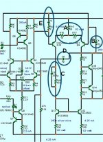
Are you sure ? what are R15-17?(attachment 1 - A) A little change in OLG , big change in VAS current. TMC definitely worked , I just wonder whether it is really needed.
On to compensation , I now use just one Cdom (B - C4) , this works better than the original 2. What was odd was that the original 2 Cdom's seemed to sum together (unity gain "UG" was my benchmark). Removing the grounded base cascode from the VAS dropped my UG from 3mhz to 1.6mhz. At 1.6mhz I had the classic bode plot (attachment 2). Is 1.6 too high ??
, I simulated most of the classics (pioneer , sansui ) , they were under 1 MHZ UG. I saw they used either (E - attachment 1) , an R - C in the diff. ,or some form of (D - att. 1) , lead compensation either from the OPS or directly from the VAS.On the mongrel , these techniques essentially did the same thing , as seen in [attachment 3] , dropping unity gain to 600-700khz and extending phase margin to higher frequencies. I just wonder which is best ?? .. compensating before (differential) or after (lead comp). various manufacturers seem to do it both ways.
OS
Attachments

Last edited:
Ostripper, would I be right to say that the point in changing compensation would be an improvement in 20KHz spectrum profile? If so, there are two criteria I know of - distortion injected through the caps (especially C4 and C5), and the speed of the amplifier.
I do my best to keep capacitors away from the output stage. I mentioned in post 82 a method that I just simulated and was able to get adequate phase margin using, without any liable capacitors. Stuart's suggestion may be good, but it doesn't completely accomplish this. I haven't tested both, but I will.
Also, the d(x) plot function is a MUST! Use it! It will show you the higher order components in a trace. Use it on the compensation capacitors to see which ones carry the largest error currents.
- keantoken
- Status
- This old topic is closed. If you want to reopen this topic, contact a moderator using the "Report Post" button.
- Home
- Amplifiers
- Solid State
- The MONGREL (supersym II)