Exactly, by manipulating the Ltspice commands, when one doesnt need to do this, what does it tell you of the circuit.
I have trouble understanding what you mean here...
I'm on page 6 of all the posts you've ever made.
") Right now it seems you like cascoded LTP, baxandall super pair or folded cascode VAS... Perhaps a combination? But so far nothing really matches well with the information you've given me... It seems to me that for your amp to be so good with so little OLG you would need an incredible VAS (crossover spikes are often induced through Cdom or Cob of VAS), and I think a baxandall super pair-folded cascode might fit the bill. Haven't had any sims yet...
Right now it seems you like cascoded LTP, baxandall super pair or folded cascode VAS... Perhaps a combination? But so far nothing really matches well with the information you've given me... It seems to me that for your amp to be so good with so little OLG you would need an incredible VAS (crossover spikes are often induced through Cdom or Cob of VAS), and I think a baxandall super pair-folded cascode might fit the bill. Haven't had any sims yet...- keantoken
No wonder the Cyrus is finicky, the compensation scheme is otherworldy. There was certainly a great amount of attention given to the compensation. It seems like an insane thing to try and market. If I posted such a design here, I would get 30 people telling me how unstable it is, how unlikely it would be for me to get it to work, only in simulation, etc.... Only comes to show, there's no free lunch in the world. If you want something good, you must give proportionate effort (to get it stable, for instance...). And when you do, look at the result...
But I think this is just with the Cyrus, not all triple EF amps are like this surely.
- keantoken
But I think this is just with the Cyrus, not all triple EF amps are like this surely.
- keantoken
Kean dont waste your time with my older posts, you will not find any clue to this amp, I promise you, I do have other amps I used through the years, I built amps since i was 12, RF ones, then audio ones. You could find clues to previous efforts but not this one. Btw I was never able to build a baxandall that didnt oscilate in the Mhz region. A baxandall super pair folded cascode ???? ...... I like your thinking might give me more ideas for a future amp, but I dont think Ill manage another design with this performance and so little active parts but its hell building it. Transistor matching takes as long as building up a pcb and you end up with many leftover parts, in the frontend Im using higher performance small signals which I dont have models for but I simmed with fairchilds 1845.
Os theres no secrets, theres just no margin of error allowed when building it, from the sims you can see Im not using any kind of trickery, my spice commands are simple and there for anyone to see. Even using 4 less active components in my frontend which would mean less parts than even a D self amp frontend this amp will beat his on THD, slewrate and what ever figures the good doctor can think of.
Os theres no secrets, theres just no margin of error allowed when building it, from the sims you can see Im not using any kind of trickery, my spice commands are simple and there for anyone to see. Even using 4 less active components in my frontend which would mean less parts than even a D self amp frontend this amp will beat his on THD, slewrate and what ever figures the good doctor can think of.
I've simulated an amp that will slew to 600V/uS. By this time the input stage is operating in class AB...
Not to worry Homemodder, by the 8th page my zealousness was beginning to wear off. I'm happy for now to wait and see whether you are given permission to post the schematic.
- keantoken
Not to worry Homemodder, by the 8th page my zealousness was beginning to wear off. I'm happy for now to wait and see whether you are given permission to post the schematic.
- keantoken
I really would like to get the model for the 1166 but LT does not list it .
If anyone knows where to get it , please tell.
all these secrets... ohhhhhhhh
OS
I update LTspice often, the 1166 is in the lib.
the 1166 is in the lib.
Where?? i've looked for it.
found it .. special functions..
Last edited:
Os theres no secrets, theres just no margin of error allowed when building it,
True , but that in itself might be a secret or elusive to some.

Saw the cyrix 1 , actually got it to work by tinkering around. The "otherworldly"
compensation is now another "trick". Wonder
why it is taboo to post cyrix info , are they some sort of holy amp (grail), looked simple to me ??OS
I think Anatech was in the business with Cyrus, I've seen him posting help for fixing them. Dunno.
- keantoken
Right on, which model did you sim btw???
Lt1166
Forget that kludge.
Hi OS,
According to Bob Cordell it is NOT that easy.
See:http://www.diyaudio.com/forums/anal...orch-preamplifier-part-ii-57.html#post1892313
http://www.diyaudio.com/forums/soli...l-interview-bjt-vs-mosfet-56.html#post1207923
JC: http://www.diyaudio.com/forums/soli...l-interview-bjt-vs-mosfet-57.html#post1207036
NP: http://www.diyaudio.com/forums/soli...terview-error-correction-325.html#post1479121
And please, don't do this: http://www.diyaudio.com/forums/anal...orch-preamplifier-part-ii-59.html#post1894057
And here you can find a model: http://www.diyaudio.com/forums/soli...terview-error-correction-321.html#post1478092
plus a schematic of the internals: http://www.diyaudio.com/forums/soli...terview-error-correction-329.html#post1485140
Cheers,
E.
BTW , the krill's non- switching behavior also degrades with level/load.
Forget that kludge.
IF you want FULL non-switching get a couple of LT1166's (IC below) link: http://cds.linear.com/docs/Datasheet/lt1166.pdf
I might add this as an add-on to this amp , VERY easy to implement.
OS
Hi OS,
According to Bob Cordell it is NOT that easy.
See:http://www.diyaudio.com/forums/anal...orch-preamplifier-part-ii-57.html#post1892313
http://www.diyaudio.com/forums/soli...l-interview-bjt-vs-mosfet-56.html#post1207923
JC: http://www.diyaudio.com/forums/soli...l-interview-bjt-vs-mosfet-57.html#post1207036
NP: http://www.diyaudio.com/forums/soli...terview-error-correction-325.html#post1479121
And please, don't do this: http://www.diyaudio.com/forums/anal...orch-preamplifier-part-ii-59.html#post1894057
And here you can find a model: http://www.diyaudio.com/forums/soli...terview-error-correction-321.html#post1478092
plus a schematic of the internals: http://www.diyaudio.com/forums/soli...terview-error-correction-329.html#post1485140
Cheers,
E.
Thanks for the links Stuart.
Homemodder, how do you like this? 60V pk-pk into 8 ohms, 68db GNFB. Perhaps with some more mods...
The output bias setting will largely factor in to the harmonic profile. I still don't know exactly how I should choose a bias setting. Slightly overbiasing decreases ultrasonic trash at the expense of H7 and co. "correct" biasing the way I figure it, decreases H7 and thereabouts at the expense of ultrasonics.
- keantoken
Attachments
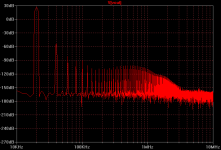
I still don't know exactly how I should choose a bias setting.
.step param Rbias 20 200 20 . If your Rbias is a 200R trimmer , for example. Replace the value of the trimmer with {Rbias}.
Simulation will create ten distortion residual reports in error log as well as 10 FFT's .
I was more uncertain about how one should pick the bias point WRT harmonic profile.
Exactly , with the step , short of having a multi -1K$ distortion analyzer .. you can at least come CLOSE to an OPS's "sweet spot". Take for instance the smaller NJW0281 vs. the big MJL21193 , the 0281 likes 40-50ma and the monster 21193 likes 70+ for lowest THD. This I have confirmed on the real thing.
What was nice was that I knew before I actually had the screwdriver on the trimmer. You can also step to find optimal compensation (.step param Cdom 20p 100p 10p). You have as a result a compound bode plot showing all possible slopes and phase relationships vs. dominant pole. (example below)
scope = 20mhz hitachi dual trace , used lightly by salt lake city schools (clean , but needs probes ... already found PDF manual)
OS
Attachments
Last edited:
Ostripper, can your scope do differential? One channel should have an "invert" button so the trace displayed will be the residual between the two inputs. A trick for you: put one probe at the base of one of the drivers, the other at the output. Vary the sensitivity of one of the channels until you've canceled out the fundamental and you can see the residual. You can visually tune the amp's bias this way. You could even listen to the distortion if your scope has a "signal out" connector.
- keantoken
- keantoken
- Status
- This old topic is closed. If you want to reopen this topic, contact a moderator using the "Report Post" button.
- Home
- Amplifiers
- Solid State
- The MONGREL (supersym II)