is this the "dynamic bias mis-tracking" that Cordell mentions regularly when talking about TMC and TT diodes?..............TMC/no TMC sounded about the same at normal volumes , at moderate to high volumes , TMC had more clarity, depth ... the image deepened.. ..............................
I settled on 470R / 100 - 430p for all 4 amps. TMC was noticeable at high volume , and if I reduced the output stage bias. In NO WAY did the extra cap and FB resistor degrade the sound at ANY volume or in any of the combinations that I tried.
As the junctions get hotter, the bias mis-tracks and then TMC gets the chance to show how well it works at reducing the need for very accurate bias setting with delta Tj.
what is the difference between fft4 & fft5 in post930. The lower high harmonics of fft5 look much nicer.
Last edited:
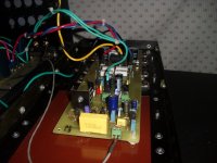
BX1.3 and CX1.3 comparison
Hi OS,
Congratulations on your excellent modular project. Sorry to hear you blew up your CX1.3. Did you manage to compare it with the BX1.3 before that happened and, if so, what did you conclude during your listening tests? Re your post #888.
Regards,
currentflow
Hi OS,
Congratulations on your excellent modular project. Sorry to hear you blew up your CX1.3. Did you manage to compare it with the BX1.3 before that happened and, if so, what did you conclude during your listening tests? Re your post #888.
Regards,
currentflow
My answer to Os
Hi Os, glad that you liked the circuit, yes a joint to develop this little monster would be very productive, I am open to suggestions to improve this circuit. This topology is plain simple and strait forward (somewhat old fashioned).
Some explanations:
1) A complementary input deals better with distortion as Ic=f(A^e(B*vbe-1)), so when the upper half increases the current the second derivate d((dIc)/d(Vbe)) decrease (enters a 'more linear' region) which produces a distribution where even harmonics are more dominant, at this time the lower leg is decreasing current, it enters a 'more curved' region where the odd harmonics are more dominant. It is known that high current excursions reinforces odd harmonics over the even harmonics, producing the unpleasant hearing sensation. A differential amp indeed lowers THD but subtract the even harmonics (the pleasant ones), more than odds. Thats why I've choose this topology. Anyway it is known that differential amps lowers THD wich is always good (used at input and the VAS).
2) Q12 and Q14 makes a quasi-differential VAS (Q11,Q13) halfing THD (in theory lower the evens), but the most important function is to add stabitity with little Cdom (27 pf) via C5,C6 which act as dumpers killing rapidly overshoots with a little sacrifice of BW abd THD (I've simulated square waves and clipping at 100KHZ to MHZ's without problems), so you can obtain a wide BW and high slew rate, in this case 200V/usec. This way you can use as little input degeneration as posible (which favours low THD) rise OLG (which favours THD again via NFB) without the risk of instability, the amp presented has Av(OLG)=120000. This circuit has an OLG small signal THD of 0.05% wich is very low for such gain.
3) The complementary buffer is very important as I taked away the Vbe multipler from the VAS (I found that introduces a little distortion, via the imbalace of output impedance of the VAS) and replaced by the old diode string. If this stage (including diodes) are thermaly coupled with the power followers, as temperature rises the current bias lowers, helping the risk of thermal runaway.
5) I know that darlingtons has bad reputation working in parallel, thats why are 4 totems (750ma each) with strong degeneration (.68 OHMS) to maintain a secure margin over the SOA curve, and this devices has 10x ft over MJExxxxx. I've simutated with HEXFET too (what I have on hand), but first the models are no reliable and second it performed worst in simulations due the very nonlinear nature of stored charge in the gate at high frecuencies, to overcome this the need of a ridiclous low impedance buffer (note the buffer presented has 0.75 OHMS and was'nt satisfactory), maybe lateral MOSFET behave better, but vertical are a mess, not for this circuit. The parallel darlintons offer also a very good dumping factor as output impedance is 0.001 OHM.
4) I know the servo is an issue, but creating additonal feedback paths may thwart the circuit introducing unwanted zeros (i have only two, one at 20MHZ and Cdom at 216MHZ), it is open to investigation. That's why I opted an integrator to bias the current of the input legs (dependant CCS = no LED but a 1N4148 to follow transistor Vbe thermal change) minimizing it's influence into the signal path, but fast enough to track thermal changes, the maximum deviation instantaneous deviation of dc offset (at low frec.) is about 15mVolts, after a second is set within 1mVolt or less, and Q12,Q14 helps to minimize the DC offset too at frecuencies of 1KHZ and above.
Os, I am sketching some drafts to develop the PCB, but if you want to do a PCB, no problem at all, you will be the first hearing this thing ha ha ... my schedule is one month as minimum as I do this in my spare time. For me it's a must to put a ground plate and shield the tracks to avoid 'antennas' as much as posible, but don't see any critical issue, as there are'nt high impedances over the circuit that may catch spurious radiation or microphony. Other thing important is to avoid the parallel capacitance over the feedback path (this would be very nasty), anyway it is a low impedance path.
I am open to send more details on request.
Cheers
Arturo
PS apoligies for the typos, I speak spanish.
Artu , If you have a LT (what do you use for simulation??) file. Post it (base .ASC and a .inc text of any models exclusive to the sim).
I did get the CX to work after it fried a few devices by removing the beta enhancement. At this point it was essentially my "supersym w/ cascode. It sounded "nice" but is not in the same league with the 2 blameless's (AX/BX).
The blameless's w/ tmc are TRULY blameless...")
Yes , you are correct. Especially on a standard (NO t-trak)OPS , a dynamic mistracking of Vbe occurs on transients because the Vbe can't keep up with the millisecond to millisecond thermal peaks and valley's of the OP. With TMC , this is why I noticed it's effect at moderate to higher volumes. TMC will totally cancel out any switching distortion right down to class B operation (0 bias - confirmed static bias on CRO) ,so any dynamic mistracking is a "walk in the park" for this compensation method.
At lower volumes (first watt) , especially with 4 pair outputs @ 80ma ea. ,you are essentially in class A most of the time anyways.
OS
By currentflow - Congratulations on your excellent modular project. Sorry to hear you blew up your CX1.3. Did you manage to compare it with the BX1.3 before that happened and, if so, what did you conclude during your listening tests? Re your post #888.
I did get the CX to work after it fried a few devices by removing the beta enhancement. At this point it was essentially my "supersym w/ cascode. It sounded "nice" but is not in the same league with the 2 blameless's (AX/BX).
The blameless's w/ tmc are TRULY blameless...
By andrew T. - is this the "dynamic bias mis-tracking" that Cordell mentions regularly when talking about TMC and TT diodes?
As the junctions get hotter, the bias mis-tracks and then TMC gets the chance to show how well it works at reducing the need for very accurate bias setting with delta Tj.
Yes , you are correct. Especially on a standard (NO t-trak)OPS , a dynamic mistracking of Vbe occurs on transients because the Vbe can't keep up with the millisecond to millisecond thermal peaks and valley's of the OP. With TMC , this is why I noticed it's effect at moderate to higher volumes. TMC will totally cancel out any switching distortion right down to class B operation (0 bias - confirmed static bias on CRO) ,so any dynamic mistracking is a "walk in the park" for this compensation method.
At lower volumes (first watt) , especially with 4 pair outputs @ 80ma ea. ,you are essentially in class A most of the time anyways.
OS
Last edited:
There isn't.
It looks better to some on the schematic though.
As far as porting a leech clone to a voltage stage , only 14 transistors...
8 for LTP/cascode -2 for CCS's - 4 for the VAS.
2 more advantages , the leech loves to run HOT... 12-15ma VAS current and the fully comp. VAS has low inpedance (vs. a blameless or bootstrap current source) and will pull those pesky charges out of the drivers faster.
I have noticed (at least in simulation) that this type topology has faster slew "natually" (with the same 47p comp vs. a "blameless") , I can only assume this is why ???
- symmetric slew as well OS
The circuit and models
Os I use ngspice in Linux and Spicef3 version 5 on FreeBSD (no Windows). Both simulators shows same result. This simulator does not use the BJT NK (flicker noise) parameter. All the models I beleive are from reliable sources ON Semi, Fairchild, Zetex. As I explained I only have a text file (.cir), so to use it with LTSPICE or other graphic front end you'll need to generate your own .asc file, but you can cut and paste the models I use, and also check the schematic I've posted wit the .cir file (I am an old man form the unix days). Inside the .cir file there are lots of models not used, and there are replicas of the same model (different sources) with slight differences to add more reality and imbalance. The file attached amp4.txt is what you need to simulate. Ahh to simulate slew rate you must bypass the input capacitor and connect the servo out to GND, to disable it (because it with mess the bias as the output signal integral =/= 0.)
Cheers
Arturo
Attachments
Os, a beta enhacer is a risky option, it adds BW, OLG, reduces THD but it also add instablilty, as it raises the impedance of the input stage, and add a little to group delay. This lowers the frecuency a second order zero, so the hole OL amplifies it better. There are several misunderstanding of what NFB is. It can be viewed as a sort of memory, it acts perfectly with 0 phase shift (or 0 group delay) or if the velocity of the wave were the same for all frecuency spectrum, this does'nt hold in reality. So NFB acts as a maligne memory (it turns into a PosiveFB) for certain frecuencies (harmonics) = oscilator. In every amplifier no matter it's topology a factor named K (stability factor) must be greater or at least = 1 (at maximum gain). In a lab you can measure (obtain) the Y Z or S equivalent parameters for a 4 port device (the amp) at different frecuencies without destroying it.
K = (1 + |delta|² - |S11|² - |S22|²) / (2*|S11*S21|) >= 1
delta = S11*S22 - S12*S21
Also TMC must be crafted carefully (It adds a zero at risky frecuency spectrum), usually it detriments clipping stability in the absence of a soft clipping artifact, my take is that this complexity can be handled better by other means.
Cheers
Os, a beta enhacer is a risky option, it adds BW, OLG, reduces THD but it also add instablilty, as it raises the impedance of the input stage, and add a little to group delay.
Cheers
Yeah , I know
... boom! (CX) But it does work nice on a single 2sa1381 (blameless).
OS
Hi all, for those interested to obtain the S (scattering) parameter of your amp there are several sites that show the arrangement to do it (google it), and also posible to spice at simulation level
Measuring S-Parameters - Winter 2001
shows how to do it, now with data output of the plots and with a good HP calculator (complex arithmetic) or math software or even SPICE itself calculate K, K less than 1 = oscillator, greater than 1 but close to 1 means potential danger 2 and upper means your circuit will behave rock solid.
Cheers
Arturo
Stunning results, Artu, very nice circuit, like it a lot.....
Very high OLG, too, congratulations!
Hugh
Looking a bit deeper, these results are better than most think. Normally at
10kHz, Xover artifacts show up as higher order components - and here
there are virtually none.
It is a textbook perfect spectrum which normally very uncommon at HF.
How much class A bias is this amp running?
T
Looking a bit deeper, these results are better than most think. Normally at
10kHz, Xover artifacts show up as higher order components - and here
there are virtually none.
It is a textbook perfect spectrum which normally very uncommon at HF.
How much class A bias is this amp running?
T
It's just a simulation.
Look (below 1/2) , I can get this without tmc.. (more advanced "carlos Blame ES" - bootstrapped cs) .7ppm @1kWith just a little "magic" - (below 3 - but with a current sourced blameless).
Under 120db you can't really hear any harmonics ,maybe.. just input pair noise.
Now , in the REAL world .... (pix 4) can you really hear the differences between 2 amps that flirt with PPM ???
With brushes , cymbals , and vocals .. it is a close call ... 2 perfect amps. The bootstrap has a tiny bit more authority in the bass (that amp Below can bottom out my peerless's - easily). The AX and its TMC (which , by the way.. works much better with a CCS'ed VAS)
can exceed ANY AMP I EVER HEARD >> ABSOLUTELY !!! in the soundstage and detail at the 200 watt level. Send stinkin' shivers up your spine and there is no fatigue ... you are waiting to hear the next note like a fiendish drug addict.
I was even running the un tmc'ed BX on the left and the TMC'ed AX on the right (listening to them now - can't stop)... These are on a new level. Carlo's blame with better parts and design (matched/cascoded LTP) is a real winner to be able to come close to the mighty AX - unmatched clarity !!
Such simple circuits , who would believe
... Goldmund can go to hell. (8$ AX VB and $30 output board / below - last)OS
Attachments
I am glad you have not compared with Carlo's Dx Blame ST or even Supercharged
because if you did, would not be so happy that way.... music is celebrating your joy...but do not test..keep the way things are....hmmmm..much better i ensure you.
My 20 cents...do not do a decent A to B comparison, to keep all that happy spirit you are suggesting to us.
"dream a little dream of me"..is the music came to my ears.... if you want to make a test...do it after Christmas...will be much better this way.
picture made special for ya dear Ostry...means... are you sure?
http://www.youtube.com/watch?v=r_070zWcEuk
regards,
Carlo's
Attachments

Last edited:
heheheh.... build this one from OS.... all these Blameless style sounds very well
and you already build mine..... now it is Ostripper time.
Difference while comparing, from mine to OS will be so small that you will not feel bad because made one or other choice.
As you will never compare....then will never know.
regards,
Carlos
and you already build mine..... now it is Ostripper time.
Difference while comparing, from mine to OS will be so small that you will not feel bad because made one or other choice.
As you will never compare....then will never know.
regards,
Carlos
Last edited:
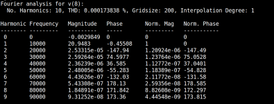
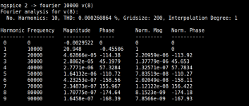
The current bias details.
Terry, to be little more illustrative: at mid power ~ 30 Watts the first fourier analysis shows weak Class A (underbiased near AB) lower THD but the 3rd harmonic as high as the 2nd. The second analysis at the correct bias shows higher THD but the optimal harmonic distribution for musicality (as tubes do).
Cheers
Arturo
Attachments
- Status
- This old topic is closed. If you want to reopen this topic, contact a moderator using the "Report Post" button.
- Home
- Amplifiers
- Solid State
- The MONGREL (supersym II)