Tommorrow I will fire up the GX's with this test voltage.
OS
I love the smell of burn'n stuff in da morn'n!

Juz fun'n - couldn't resist.
Attachments

Building MONGREL amp using recycled parts
I recently scapped a JVC (Victor) Surround amp and that gave me heaps of parts for DIY projects. First at all, the amp is about 20 years old and it cost me an arm & a leg when I bought it new. It gave crackening sound when I turned it on, I had it repaired but the problem resurfaced after a while.
I have gutted the amp and used the case & heatsink for a SymAsym and I have got 5 pairs of Sanken OTs & 2SB649 & 2SD669 plus heaps of mylar caps.
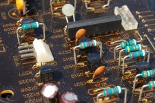
For the MONGREL project, I can use the following parts in the pictures:
2SA970 & 2SC2240 SSTs
Neatly wound output coil
White right-angled pins to connect the VB to the PB
Mounting bolt for OTs
10 Ohm (2W) resistors
May be 3900pF Mylar (Blue) capacitor for CCS C-B bypass, I think that is close enough to the 5600pF for bypass purpose.
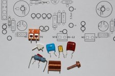
I have some questions about the capacitor types:
Maroon - value 334 - mylar (polyester)
Blue - value 392 - I think it is also mylar (polyester)
Yellow with foil inside - value 392 - I don't know what this is??
Cheers, Stanley
I recently scapped a JVC (Victor) Surround amp and that gave me heaps of parts for DIY projects. First at all, the amp is about 20 years old and it cost me an arm & a leg when I bought it new. It gave crackening sound when I turned it on, I had it repaired but the problem resurfaced after a while.
I have gutted the amp and used the case & heatsink for a SymAsym and I have got 5 pairs of Sanken OTs & 2SB649 & 2SD669 plus heaps of mylar caps.
For the MONGREL project, I can use the following parts in the pictures:
2SA970 & 2SC2240 SSTs
Neatly wound output coil
White right-angled pins to connect the VB to the PB
Mounting bolt for OTs
10 Ohm (2W) resistors
May be 3900pF Mylar (Blue) capacitor for CCS C-B bypass, I think that is close enough to the 5600pF for bypass purpose.
I have some questions about the capacitor types:
Maroon - value 334 - mylar (polyester)
Blue - value 392 - I think it is also mylar (polyester)
Yellow with foil inside - value 392 - I don't know what this is??
Cheers, Stanley
Attachments
Yellow caps
Thanks keantoken,
I have seen polystyrene caps - they are transparent cylindrical case with visible foil inside. These yellow ones are a bit different and they are also used in the LP filter section after DAC inside my blu-ray player, the value ranges from 1500pF to 47nF. I have attached another picture here.
Cheers, Stanley
Attachments
The GX lives ... ha ha ha
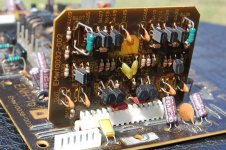
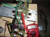
I fired up the GX's , at first forgot to hook up the NFB wire. What I did.. is use a 35-0-35v supply to "test fire" the circuit. On first try ,one led would not light up , no smoke but something was wrong. 10R safety resistors were cool as was everything else. Forgot to give the poor amp NFB !!! Fixed that , have 32mv offset at OP without adjustment.
I used "fake" 33R emitter resistors to just power the drivers up and I get +651mv and -685mV on the driver emitters. This seems to be close to spec even at half rail voltage. Final pix is a voltage test of the whole GX at 35-0-35V.
OS
Attachments

Hi OS,
Good works, I have been wondering where NFB goes. I guessed that I should add a jumper to the PB120 layout from NFB to somewhere near the output coil pickup point, roughly midway between the OTs.
I may add the voltage regulating section from the PB250 to the PB120 layout.
Do I lose a few volts by using regulator for the VB?
Cheers, Stanley
Attachments
Hi OS,
Good works, I have been wondering where NFB goes. I guessed that I should add a jumper to the PB120 layout from NFB to somewhere near the output coil pickup point, roughly midway between the OTs.
I may add the voltage regulating section from the PB250 to the PB120 layout.
Do I lose a few volts by using regulator for the VB?
Cheers, Stanley
You lose 1.7v with 35.8-0-35.8VDC (that is exactly what the little trafo gives me) with 75v+ I expect about a 2v loss.
I am now at the full power 77-0-77VDC stage of my "burn-in" WITH 1 pair of outputs. Wish me luck.
OS
NFB, optimally, should come say a mm after the output takeoff point, so distorted currents don't squeeze past the NFB takeoff into the output takeoff. That's how I understand it.
- keantoken
quite right , man.. like below , right at the inductor(Below). On the horizontal layout it is more critical since the distance the current has to travel across traces is far greater.
OS
Attachments
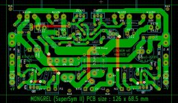
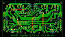
I added the voltage regulator from PB250 to PB120LP. I also moved pickup point for the output coil to the midway between the OTs. This one should be all good.
Cheers, Stanley
Is that what kind of trimmer they have "down under", up here the trimmers are 3 X 2.5mm inline style ... This

or this..

OS
Is that what kind of trimmer they have "down under", up here the trimmers are 3 X 2.5mm inline style ...
OS
Hi OS,
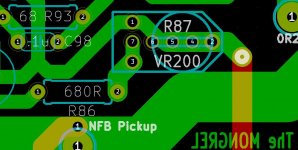
You have reminded me - I have changed the trimpot footprint to the universal one; so that it can fit more than one type of trimpot, including the 3 x 2.5mm in-line style.
BTW, do we have minimum bias current for maximum resistance (200 ohm in this case) ??
Attachments
Hi OS,
BTW, do we have minimum bias current for maximum resistance (200 ohm in this case) ??
Tried that my self , with the GX/PB250 , an open trimpot (which will be 200R) gives + and - 500mv at the driver emitters which would be fully class B (no bias)
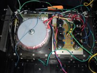
A shorted trimpot will bias the OP's at over 250mA , so we have a healthy range as well as a safety margin. I have 1 pair OP's hooked to the "monster" (below) running 1 small 2-way (sounds good). I must "break-in" the other amp with 1 Pair as well to ensure electrical and thermal stability as well before I populate all 16 OP devices. I will never again smell the "magic smoke". I am sure a small value change will be done to the VBe before I am done. I miss the massive headroom of my "supersym" already , my little Dx clone just doesn't cut it...
OS
Attachments
Parts list
Hi, OS
I am checking the BOM against the schematics for GX1.2VB & found some discrepancies. I believed that the BOM is more up-to-date.
I found most of the parts from Farnell & they do not charge shipping for local deliveries.
I have found some challenges with some capacitors:
C2 - 330pF, 100V ceramic - I have Wima FKP2 (1000V) in my parts bin so I will use this Polypropylene type.
C3 - 220uF/35V Non-polar. Farnell does not have these at reasonable price. I normally use low-voltage polar electroyltics in this position & I have got a couple of 470uF (16V) Panasonic FC type in my parts bin.
C8 & C9 - 0.68uF ceramic 100V - I can only find Kemet Z5U 0.68uF (50V) on Farnell & my power supply is only 42V DC.
C5 - 0.01uF ceramic 100V - I can only find Kemet COG 0.01uF (200V) on Farnell & I think that this is spot on.
C7 & C9 - 47pF silver mica - again I have Wima FKP2 in my parts bin so I will use them for test & I can buy Silver mica from a local shop later.
All up, my Farnell order is less than $20 and I have to buy some 2SC3503/2SA1381 transistors & trimpots from the local shops.
Thanks & regards, Stanley
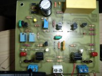
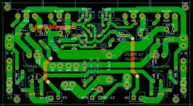
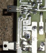
A pix is worth many words (below).
EDIT- blue cap at far left is the CCS C-B to ensure stability of high gain CCS (5600pF).
os
Hi, OS
I am checking the BOM against the schematics for GX1.2VB & found some discrepancies. I believed that the BOM is more up-to-date.
I found most of the parts from Farnell & they do not charge shipping for local deliveries.
I have found some challenges with some capacitors:
C2 - 330pF, 100V ceramic - I have Wima FKP2 (1000V) in my parts bin so I will use this Polypropylene type.
C3 - 220uF/35V Non-polar. Farnell does not have these at reasonable price. I normally use low-voltage polar electroyltics in this position & I have got a couple of 470uF (16V) Panasonic FC type in my parts bin.
C8 & C9 - 0.68uF ceramic 100V - I can only find Kemet Z5U 0.68uF (50V) on Farnell & my power supply is only 42V DC.
C5 - 0.01uF ceramic 100V - I can only find Kemet COG 0.01uF (200V) on Farnell & I think that this is spot on.
C7 & C9 - 47pF silver mica - again I have Wima FKP2 in my parts bin so I will use them for test & I can buy Silver mica from a local shop later.
All up, my Farnell order is less than $20 and I have to buy some 2SC3503/2SA1381 transistors & trimpots from the local shops.
Thanks & regards, Stanley
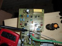
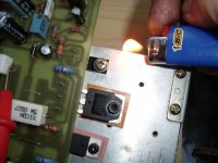
Continuing my SLOW , thorough tests on the GX1.2VB/PB250 combo. With both 77V rails and 36V rails (SNG001 , I would not use the cap multipliers.. you lose 3 v AND 2V through the hawksford cascodes) , The Vbe is ROCK solid with a range of 0 Mv (last turn on trimmer) to 84mv (300ma bias) Pix 1 is after a 10C cold morning .. stayed at 22-23mV all day even after the 32C high (hot day). NO mods need to be done to this important circuit. It is very fast , use a lighter to check it..(pix 2) Ha Ha.
It sounds great ... with only 1 pair OP's , about the same if not a little more detailed than the symasyms .. VERY nice high frequency reproduction.
With the modular design , once the PB250's are locked in , I will adjust any compensations easily. I don't expect very many issues with this .. as EVERY simulated aspect has panned out exactly as LT predicted , right down to the mV.
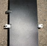
Edit , this is what I envisioned for the VAS heatsink(pix 3),made from a small piece of roof flashing , runs nice and cool..
OS
OS
It sounds great ... with only 1 pair OP's , about the same if not a little more detailed than the symasyms .. VERY nice high frequency reproduction.
With the modular design , once the PB250's are locked in , I will adjust any compensations easily. I don't expect very many issues with this .. as EVERY simulated aspect has panned out exactly as LT predicted , right down to the mV.
Edit , this is what I envisioned for the VAS heatsink(pix 3),made from a small piece of roof flashing , runs nice and cool..
OS
OS
Attachments
Last edited:
SNG, you could try photoflash caps if you have some. I wonder if these aren't the "next step up" so to say from normal electrolytics. I'm using them in the feedback shunt cap currently and the difference in sound worth investigating I think.
- keantoken
I've just tested a slew of caps in the feedback shunt network. Photoflash won, I can speak from experience now. My cap came from a clip-on flash unit, and is more powerful than what you usually find, 330V 200uF.
So I encourage others to try and want to hear the results, if so...
Originally posted here:
http://www.diyaudio.com/forums/head...phone-amp-jlh-output-stage-8.html#post2303403
- keantoken
Last edited:
Don't have any of those caps , Keen.. what I do have is two killer amplifiers . Below is the final tested 78 volt rail readings off the actual circuit.
For those using 35-50v , NO adjustment is needed , save for a slight tweak in the CCS and Vbias trimmers. NO turn on thump , NO noise at all (silence) , 1mv offset with just half turn of the trimmer and best of all ..no stability issues AT ALL.
The 35v readings are just a matter of subtracting 43 volts from every 78V reading. LED Vf drops slightly at 35V rails (2.2@78 -1.9@35v).
I forgot the NFB hookup TWICE , amps did not blow but just went to the positive rail making one green LED not illuminate. A VERY forgiving circuit. BEWARE , do not touch input with finger , 60-70VAC at OP will fry your speakers ... 38DB gain is scary.. Total success , now I have to machine my heatsinks (layout,drill ,and tap) with all 4 Op pairs ...this will be one good project.
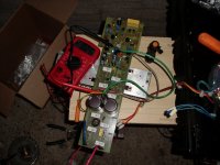
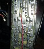
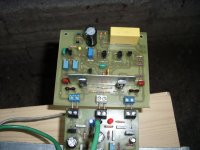
A few ideas/examples on how to have a safe power board are pix 2 and 3. Black insulator is a polyethylene notebook cover cut to cover the board while allowing for power device thermal contact. Outputs/drivers should be mounted like in last picture 3-4mm off of board , try to space the driver holes 102mm (4") and the output holes 115mm (4 1/2") apart for mounting on a 5" /120-125mm heatsink.
OS
. Below is the final tested 78 volt rail readings off the actual circuit.For those using 35-50v , NO adjustment is needed , save for a slight tweak in the CCS and Vbias trimmers. NO turn on thump , NO noise at all (silence) , 1mv offset with just half turn of the trimmer and best of all ..no stability issues AT ALL.
The 35v readings are just a matter of subtracting 43 volts from every 78V reading. LED Vf drops slightly at 35V rails (2.2@78 -1.9@35v).
I forgot the NFB hookup TWICE , amps did not blow but just went to the positive rail making one green LED not illuminate. A VERY forgiving circuit. BEWARE , do not touch input with finger , 60-70VAC at OP will fry your speakers ... 38DB gain is scary.. Total success , now I have to machine my heatsinks (layout,drill ,and tap) with all 4 Op pairs ...this will be one good project
.A few ideas/examples on how to have a safe power board are pix 2 and 3. Black insulator is a polyethylene notebook cover cut to cover the board while allowing for power device thermal contact. Outputs/drivers should be mounted like in last picture 3-4mm off of board , try to space the driver holes 102mm (4") and the output holes 115mm (4 1/2") apart for mounting on a 5" /120-125mm heatsink.
OS
Attachments
Last edited:
Cap multiplier
Hi OS,
Do you mean the voltage regulator that I added from the PB250?
I can easily bypass it by using the latest layout by installing only the R78 (22R) & C72. I have highlighted yellow in the attached picture.
- Stanley
(SNG001 , I would not use the cap multipliers.. you lose 3 v AND 2V through the hawksford cascodes)
OS
Hi OS,
Do you mean the voltage regulator that I added from the PB250?
I can easily bypass it by using the latest layout by installing only the R78 (22R) & C72. I have highlighted yellow in the attached picture.
- Stanley
Attachments
- Status
- This old topic is closed. If you want to reopen this topic, contact a moderator using the "Report Post" button.
- Home
- Amplifiers
- Solid State
- The MONGREL (supersym II)