I will be selling boards in october (GX,AX,BX,CX , PB250/60- PS100)
I am waiting for this too.
Thanks for your web site. Great work!
Transistor matching & Photoflash cap
Thanks OS,
I tested the salvaged SSTs, the BL grade are pretty well matched - I think they were matched at JVC factory.
I opened the Olympus camera & found a 160uF/330V Photoflash cap inside & I got it out.
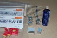
The first lot of my Farnell order has arrived. Attached is the picture of some of the parts.
Silver naked skinny cap - EPCOS B32562 series 4.7uF silver cap for C1.
Red poly caps - Wima FKP2 47pF Polypropylene, it is a bargain at 9c each.
Purple-blue electro - United Chemi-con 160uF/330V, I will use this as C3.
Silver electros - Nichicon UHD 220uF/35V, I ordered this for C3, but I think I will try the photoflash cap first.
Vishay BC SFR16 resistors - they are tiny, I can't complain as they are only 2c each and the spec is also quite good - temp coef=100ppm.
The other parts will take another week to ship from US warehouse.
Cheers, Stanley
Be sure to test all your salvaged components before using them.
OS
Thanks OS,
I tested the salvaged SSTs, the BL grade are pretty well matched - I think they were matched at JVC factory.
I opened the Olympus camera & found a 160uF/330V Photoflash cap inside & I got it out.
The first lot of my Farnell order has arrived. Attached is the picture of some of the parts.
Silver naked skinny cap - EPCOS B32562 series 4.7uF silver cap for C1.
Red poly caps - Wima FKP2 47pF Polypropylene, it is a bargain at 9c each.
Purple-blue electro - United Chemi-con 160uF/330V, I will use this as C3.
Silver electros - Nichicon UHD 220uF/35V, I ordered this for C3, but I think I will try the photoflash cap first.
Vishay BC SFR16 resistors - they are tiny, I can't complain as they are only 2c each and the spec is also quite good - temp coef=100ppm.
The other parts will take another week to ship from US warehouse.
Cheers, Stanley
Attachments
I've been looking for this page forever and finally found it again. Enjoy:
The "Sound" of Capacitors
- keantoken
The "Sound" of Capacitors
- keantoken
That 330V/160uF cap looks like an ordinary switcher cap. They may be the same thing, but mine has the words "photo-flash" marked on it. I have also seen "foto-flash" used.
I wish we could be certain about these things. In disposable throw-away cameras I believe are the obvious ones, with the photo-flash mark. I'm not sure, but Kodak may recycle these cameras (what else do they do with them when you bring them back to the store? Then again, if they just get thrown away, you should be able to get a bunch for free from the local walmart).
Thoughts from anyone more knowledgeable than me?
- keantoken
Looking at "baby amps" on the "other" thread.
They must be easy to do !! angle aluminum Gobs of thermal compound , good thing they only have 1 pair of outputs. Milling my huge heatsinks was harder than I thought , bought 2 taps (6-32 and 4-40) to do a perfect job (below 1). Now I can "plug em' in" for real ... all 4 pairs. What tough blocks of aluminum.
OS
They must be easy to do !! angle aluminum
Gobs of thermal compound , good thing they only have 1 pair of outputs. Milling my huge heatsinks was harder than I thought , bought 2 taps (6-32 and 4-40) to do a perfect job (below 1). Now I can "plug em' in" for real ... all 4 pairs. What tough blocks of aluminum. OS
Attachments
Hi,
Those "naked" caps are the same physical construction as polycarbonate.
Hi Andrew,
The following is the description of the naked Silver cap on Farnell site:
Manufacturer: EPCOS
Order Code: 9752714
Manufacturer Part No: B32562J1475K
Description CAPACITOR, 4.7UF, 100V
Capacitor Dielectric Type
olyester Capacitance:4.7µF
Capacitance Tolerance:± 10%
Voltage Rating:100V DC
Series:B32562
The EPCOS datasheet says:
Construction
Dielectric: polyethylene terephthalate
(polyester, PET)
Stacked-film technology
Uncoated
It is the cheapest 4.7uF film cap ($0.77) on the Farnell site and I guessed that I did not pay for the fancy coating.
Hi KT,
The blue photoflash cap was actually manufactured by United Chemi-con and the camera is very old (> 15 years old) so they may not adopt the special marking for photoflash cap. The camera is a first-gen digital camera so I think that costed an arm & a leg when it was new. I tested the blue cap & the leakage current is quite low.
Cheers, Stanley
Finalised BOM for GX1.2VB
Hi OS,
Can you please update the BOM for GX1.2VB?
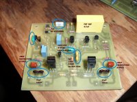
I noticed that the cap value showed in the picture does not agree with the schmatics & BOM.
BTW, what is the value for the R12 trimpot (offest adjust)? The schmatics says 500R but the BOM says 200R.
I am going to buy the trimpots from the local electronic shop this weekend so a quick reply is appreciated.
Cheers, Stanley
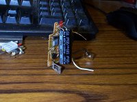
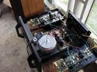
A pix is worth many words (below).
EDIT- blue cap at far left is the CCS C-B to ensure stability of high gain CCS (5600pF).
os
Hi OS,
Can you please update the BOM for GX1.2VB?
I noticed that the cap value showed in the picture does not agree with the schmatics & BOM.
BTW, what is the value for the R12 trimpot (offest adjust)? The schmatics says 500R but the BOM says 200R.
I am going to buy the trimpots from the local electronic shop this weekend so a quick reply is appreciated.
Cheers, Stanley
Attachments
Hi OS,
Can you please update the BOM for GX1.2VB?
I noticed that the cap value showed in the picture does not agree with the schmatics & BOM.
BTW, what is the value for the R12 trimpot (offest adjust)? The schmatics says 500R but the BOM says 200R.
I am going to buy the trimpots from the local electronic shop this weekend so a quick reply is appreciated.
Cheers, Stanley
Either , 500R reduces the effect on the input pair degeneration , 200R gives a quicker offset. I have 200R in the ax , 500R in the GX. using one or the other would have a VERY minor effect on the sound.
the 5600P is just "insurance" , I saw it implemented in another DIY amp and decided to be "insured". The AX has the same CCS and DOES NOT have it. Your choice, the board supports it.
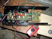
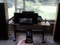
I am COCKY now , the GX has the bass of a DX style bootstrap amp , but the mids and highs from HEAVEN !! Highly recommended... Bias stays at 20mV even after 2 hours of 4R abuse. Pics of abuse below...

OS
Attachments
Madness!
Hey OS,
I'm one of the guilty who downloaded your files. I'm in the newbie category. I've got Bob Cordell's book on pre-order and you've got me pumped!
So I'll be squandering away some pennies when you have your GB and watching this thread for instructions.
Hats off! You got some skills!
Hey OS,
I'm one of the guilty who downloaded your files. I'm in the newbie category. I've got Bob Cordell's book on pre-order and you've got me pumped!
So I'll be squandering away some pennies when you have your GB and watching this thread for instructions.
Hats off! You got some skills!
I am COCKY now , the GX has the bass of a DX style bootstrap amp , but the mids and highs from HEAVEN !! Highly recommended... Bias stays at 20mV even after 2 hours of 4R abuse. Pics of abuse below...
OS
Hey OS - Grrrrrreat going and congrats!!!
Where did ya scrounge that case up from - it's very nice!!!

Hey OS - Grrrrrreat going and congrats!!!
Where did ya scrounge that case up from - it's very nice!!!
It works too good... the cops were called.

 130+ decibles will do it. Even at an estimated 150w average (saw 110v+ p/p on the oscope) the imaging is scary. Luxman had it figured .. way before hawksford.
Became quite warm after 2 hours more hours 4R load at insane levels (before the cops)but held 20mv bias perfectly.
DEFINITELY.. the best to date , by far!!
Case is the old genesis stealth minus 1/2 it's heatsinks.
OS
Luxman had in the 70's dual dif Jfet diamond buffer front end fully cascoded second stage and mosfet output oh and a separate supply for the front end. Must have been nearly ten years ahead of Dr. Hawksford's published paper. Tone controls and phono sections were very clever as well. Looking forward to your comments on how your new amp sounds. Thanks for a great thread.
Luxman had in the 70's dual dif Jfet diamond buffer front end fully cascoded second stage and mosfet output oh and a separate supply for the front end. Must have been nearly ten years ahead of Dr. Hawksford's published paper. Tone controls and phono sections were very clever as well. Looking forward to your comments on how your new amp sounds. Thanks for a great thread.
What is strange is that it sounds even better now ??? The bias is still 20mv (@75ma per device) , but it sounds even better after runnin' the snot out of it.
I wonder if the OPS has a "burn-in" .... or whether my ears were altered. (I did rest them).On the hawksford note , I came to this amps design before even reading his work or seeing the luxman , right down to the green LED's (hawksford cascode paper). The idea to decouple the emitter resistors on the cascode is mine and APT's (first saw that on the APT1).
OS
OS
Component values
Hi OS,
Thanks for the prompt reply.
I have a few questions with regards to the component value?
I referred to the schematics with voltage that you post earlier.
R2 -- -- resistor, 68K (33K on schematics)
R19 -- -- resistor, 82 (68 on schematics)
R20 -- -- resistor, 47 (33 on schematics)
R23 -- -- resistor, 270K (330K on schematics)
R24 -- -- resistor, 47 (33 on schematics)
R25 -- -- resistor, 82 (68 on schematics)
C7 -- -- capacitor, 47pF 250v (33pF on schematics)
C9 -- -- capacitor, 47pF 250v (33pF on schematics)
Can you please clarify which one (the attached schematics or BOM) is correct?
Cheers, Stanley
Attachments
Naked poly film cap (SilverCap)
Hi Andrew,
The EPCOS literature is titled:
Film Capacitors
Metallized Polyester Film Capacitors (MKT)
Series/Type: B32560 ... B32564
Date: August 2004
General purpose (stacked) SilverCapTM
Notes on mounting
When mounting these capacitors, take into account creepage distances and clearances to adjacent live parts. The insulating strength of the cut surfaces to other live parts of the circuit is 1.5 times the capacitors rated DC voltage, but is always at least 300 VDC.
Capacitors with 7.5 mm lead spacing are only suitable for use with single-clad printed circuit boards.
=-=
For me, this film cap is light on wallet & I am using single-side PCB so it suits. With reference to KT's capacitor link, any poly (film) cap should outperform electro cap in audio application.
Cheers, Stanley
I thought PET was different from MKS
What does the literature say?
Hi Andrew,
The EPCOS literature is titled:
Film Capacitors
Metallized Polyester Film Capacitors (MKT)
Series/Type: B32560 ... B32564
Date: August 2004
General purpose (stacked) SilverCapTM
Notes on mounting
When mounting these capacitors, take into account creepage distances and clearances to adjacent live parts. The insulating strength of the cut surfaces to other live parts of the circuit is 1.5 times the capacitors rated DC voltage, but is always at least 300 VDC.
Capacitors with 7.5 mm lead spacing are only suitable for use with single-clad printed circuit boards.
=-=
For me, this film cap is light on wallet & I am using single-side PCB so it suits. With reference to KT's capacitor link, any poly (film) cap should outperform electro cap in audio application.
Cheers, Stanley
- Status
- This old topic is closed. If you want to reopen this topic, contact a moderator using the "Report Post" button.
- Home
- Amplifiers
- Solid State
- The MONGREL (supersym II)