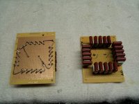
Here's a snapshot of the 1200V schottky diodes with their voltage-sharing 10nF, 1250V caps attached. All 16 of these in the picture will go into one HV bridge for the 833 B+.
I just noticed something...the caps I used across the diodes are rated for 1250VDC, so 4 x 1250V = 5000VDC, looks OK so far.
BUT, if you go into the data sheet and look around, there's a sub-data sheet that lists the maximum permissible AC as only 354V!!
Since the rectifier sees AC, I assume I need to replace these caps, correct?

I guess it's better to find out now than when I flick the switch...
I just noticed something...the caps I used across the diodes are rated for 1250VDC, so 4 x 1250V = 5000VDC, looks OK so far.
BUT, if you go into the data sheet and look around, there's a sub-data sheet that lists the maximum permissible AC as only 354V!!
Since the rectifier sees AC, I assume I need to replace these caps, correct?
I guess it's better to find out now than when I flick the switch...
To clarify, that's 354Vrms as the AC spec for those caps, which is 1000Vp-p.
So are four of those in series across the four diodes of each leg sufficient for a bridge rectifier seeing 2500V from the transformer secondary? I can't seem to find any such caps available with a much higher AC rms rating...am I getting myself worked up over nothing?
...am I getting myself worked up over nothing?
Yes, they will never see that great a potential across them as many as you're using.
Then again, I will add that when I built an HV supply for an RF tube (4100VDC), I used used ten diodes (and caps across each) per leg. Forty total! haha
Last edited:
OK, I've thought this through a bit more, because I wanted to understand why we use the DC rating and not the AC rating for the caps across the diodes in a bridge. Here's what I came up with:
When the diode string is reverse biased, it indeed sees the full DC voltage across it and across the string of caps in parallel with it. When the diode string is conducting, however, the diodes and caps see no net potential difference across them since both ends of the string are at the same potential (not counting small diode drops). So...the caps are not seeing true AC where the more positive potential switches from end to end of the string, rather they are seeing a pulsed DC turning on and off from the same end of the string.
Might be obvious to most, but it took me a while to wrap my head around it...
Caps across the diodes will not allow them to share the voltage evenly. You need resistors across the diodes for that. You just need a little bit of trickle current, so something like 2.2 Mohm across each diode should be alright. At the voltages you're working with, you need to be careful with the amount of power dissipated in these resistors... Definitely do the math.
~Tom
~Tom
")
Caps across the diodes will not allow them to share the voltage evenly. You need resistors across the diodes for that. You just need a little bit of trickle current, so something like 2.2 Mohm across each diode should be alright. At the voltages you're working with, you need to be careful with the amount of power dissipated in these resistors... Definitely do the math.
~Tom
I have read up on this for a few weeks now, and what I've found is:
a) You need resistors for static voltage sharing and caps for dynamic voltage sharing in all cases
b) You only need resistors because static voltage is what needs to be shared
c) You only need small caps because rectifier diodes have changing voltage across them
d) You don't need resistors or caps; this one was a long ham thread wherin guys with years of experience recounted how all the failures they'd seen were caused by the parallel resistors and caps
e) You should use controlled avalanche diodes with no resistors or caps
f) modern diodes are made so reproducibly that resistors and caps are now unnecessary
g) just use a much larger number of diodes than you need and voltage sharing becomes a moot point; diodes are cheap
FYI, the latest edition of the AARL handbook recommends against using either resistors or caps as they seem to cause more failures than they prevent. Previous editions recommended both resistors and caps.
My inclination is to leave it the way I have it since the diodes are rated at 4800V and the caps at 5000V in a 2300V application. The diodes are all very close in Vf (which is inversely related to leakage current) and I've sorted them into quartets with Vf with .002V apart at worst (most are identical to 3 digits).
I did do the math re: the resistors and came out with 8 megohms for the very low leakage currents quoted. Doesn't seem worth the effort, especially when most vendors don't state the voltage tolerances of their resistors - they could end up as fuses...or worse.
Here's an example of a reference where they recommend caps only, as an example:
The Valve Wizard
Merlin Blencowe being the wizard; I got his book on power supplies as a Valentines Day present...my wife knows how to butter me up.
.
.
Last edited:
Magz you can use a pair of LT1083's for a 15 amp rated filament supply FYI. It's in the data sheets as an example. They use 2 feet of #18 wire on each one to balance current sharing.
For the filaments I'm using Rod Coleman's excellent DHT supplies, which perform very well in my 26 preamp - dead silent! Thanks for the tip, though.
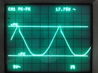
I tried to use both capacitors and resistors on my 1250v Choke input (30H) power supply for my Push Pull GM70. I had massive ringing that I couldnt solve.
I gave up and used 866 MV's in full bridge which gave no such issues.
James.
I gave up and used 866 MV's in full bridge which gave no such issues.
James.
Attachments
I tried to use both capacitors and resistors on my 1250v Choke input (30H) power supply for my Push Pull GM70. I had massive ringing that I couldnt solve.
I gave up and used 866 MV's in full bridge which gave no such issues.
James.
Interesting! What type of rectifiers, standard or schottky? Si or SiC?
I went with the SiC schottky diodes because of their lack of a reverse recovery spike, which can kick off ringing.
Hi,
They were STTA512D.
Hopefully you will not have any such issues, but it may be worth testing for!
James
Ultrafast, Si diodes with a definite reverse recovery (albeit "soft"). Hopefully the use of SiC schottkys will prevent that issue

Definitely a watch-out, though.
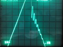
Edit: Here's the datasheet for that diode. If you look on p.7 they have a chart showing the turn-off behavior with a serial inductance - it shows ringing.
http://www.datasheetcatalog.org/datasheet/SGSThomsonMicroelectronics/mXqqsu.pdf
Last edited:
My inclination is to leave it the way I have it since the diodes are rated at 4800V and the caps at 5000V in a 2300V application. The diodes are all very close in Vf (which is inversely related to leakage current) and I've sorted them into quartets with Vf with .002V apart at worst (most are identical to 3 digits).
.
I've decided to add one more diode and cap per leg of the bridge, to give me a total of (5) 1200V diodes and (5) 1250V caps per leg, just to give me a little more headroom. I actually ordered 8 extra diodes to make the bridges for the driver circuits, and they're from the same batch as the others, so they should match pretty well.
Turns out Digikey is backordered until June for these diodes so I'm glad I ordered extra when I did, no telling how the next batch will match up with what I have. I don't need to worry about matching the ones in the driver bridges since they aren't in series.
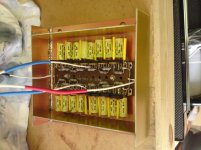
I ordered and received 8 more 10nF caps so I've been able to finish the two HT rectifier bridges (see picture).
I tested them using a variac and dialed it up to 140VAC input, getting 166VDC output in both cases. Everything worked fine, so I let them warm up a bit then I measured the voltage drops across each diode in each leg of both bridges. For the worst matched leg, the voltages varied by 4.5% from highest to lowest - translated to 600VDC across each diode, which they would see if 3000VDC were across the leg, that makes 27V difference worst case. It looks like they balance just fine using the 10nF caps across them.
Interestingly, I used 5% caps, and the worst case imbalance was around 5%...
I will probably pot each bridge in epoxy to be sure nothing can ever short out between the wiring or between the solder pads; I may remove some of the pads between the highest voltage points anyway just to be safer. It shouldn't evolve too much heat at 160mA draw so I think that potting would be the safest way to go.
.
Attachments
Last edited:
I have read up on this for a few weeks now, and what I've found is:
Rather than reading multiple internet sources and trying to take the average, I suggest thinking about what you are trying to accomplish instead. If one source says 2+2 = 4 and two sources says 2+2 = 5, what is the value of 2+2 then? 4.66?
The issue with multiple diodes in series is that you have to distribute the reverse voltage evenly across the diodes. Failure to do this will result in uneven sharing of the voltage. If one diode ends up with a lion's share of the voltage, it's more likely to blow up due to reverse breakdown. This is what you are trying to avoid. The same is the case for capacitors in series. The only device I am aware of that can facilitate this charge/voltage sharing is a resistor. Hence, each diode will need a resistor in parallel. Pick a resistor of a high resistance to avoid dissipating excessive power in the resistor. You just need a little trickle current (higher than the expected leakage current of the diodes) to facilitate the charge/voltage sharing.
The caps across the diodes will not help in distributing the reverse voltage across the diodes. In fact, they are likely to make the problem worse. Capacitors cannot conduct DC current. The capacitors are used to tame the ringing caused by the turn-off transient of the diode resonating with the parasitic LC of the secondary circuit. In my experience, these caps do more harm than good if not selected properly.
Now, you can choose to ignore physics, oversize everything, do some hand-waiving, and hope for the best. But in a $10k amplifier build operating at 2500 V with more than enough energy to kill you twice without breaking a sweat, I think you need to slow down and understand the problem rather than relying on a plug-n-play approach.
It's good to see that you are testing things at lower voltages when possible. However, note that leakage currents in the diodes is rather non-linear and very temperature dependent. In addition, you can't rely on the matching between diodes. Dude! You're playing with fire here...
I don't mean to be nasty, but this is serious stuff. 2+2 = 4 not 4.66!
~Tom
Last edited:
My experiment above seems to show they share voltage pretty well, at least at 166VDC. I didn't want to go too much higher than that and be probing around every diode with a multimeter - too much chance for a slip. Yes, I understand that leakage can be non-linear, but really how much more can that vary within the same diode batch? Probably an unanswerable question.
The problem I have with resistors is that from what I read they are usually the component that fails in these types of series bridges. I'll need to get high voltage ones for sure if I add them. Maybe I'll add some and see; I'll have to think about it.
.
The problem I have with resistors is that from what I read they are usually the component that fails in these types of series bridges. I'll need to get high voltage ones for sure if I add them. Maybe I'll add some and see; I'll have to think about it.
.
Last edited:
Mags: Wire 1 megohm 2 watt wirewound resistors across each diode in each stack. That will distribute the voltage across each diode.
Yeah, that's what I hear. I still may just because some folks seem so adamant about it, but I was curious as to see how well it would work with just the caps. Works pretty well, at lower voltages at least.
It's good to see that you are testing things at lower voltages when possible. However, note that leakage currents in the diodes is rather non-linear and very temperature dependent.
~Tom
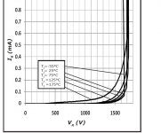
Interestingly, the datasheet from Cree shows that the Ir is quite steady with voltage and temperature up to at least 1000V per diode and 125 degC. Must be the SiC.
Attachments
- Home
- Amplifiers
- Tubes / Valves
- The Midlife Crisis - My 833C Amp Build