have you been considering other big tubes?
tri tetra penta ?
No, my heart is set on the 833.
I am, however using a tetrode as the input/driver tube, although it's triode strapped.
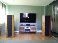
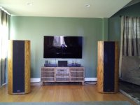
I've been sidetracked the last week getting a new flat screen TV and small media console to replace that behemoth Rear Projection CRT TV and entertainment center in the previous post with my speakers. It's all installed now and the improvement in soundstaging and depth is great! Check it out:
Attachments
Back on track...
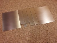
The two chassis from Landfall arrived today. The pieces are very well constructed and together should make quite a robust chassis. See picture showing parts for one 18" x 22" x 4.25" box.
Time to get this project in gear! Updates to follow.
The two chassis from Landfall arrived today. The pieces are very well constructed and together should make quite a robust chassis. See picture showing parts for one 18" x 22" x 4.25" box.
Time to get this project in gear! Updates to follow.
Attachments
sorry offtopic
but where´s this mediacenter from-looks very nice!
but where´s this mediacenter from-looks very nice!
I've been sidetracked the last week getting a new flat screen TV and small media console to replace that behemoth Rear Projection CRT TV and entertainment center in the previous post with my speakers. It's all installed now and the improvement in soundstaging and depth is great! Check it out:
but where´s this mediacenter from-looks very nice!
Crate and Barrel. It's called a "Maria Yee" 58" media center. I wanted to get a full audio rack, my wife wanted something more like nice furniture, and this is what we compromised on. It has lots of ventilation, generous cutouts for wires (although I would have preferred a completely open back...) and it's built using "Chinese joinery" supposedly with no screws or other fasteners. It's pretty sturdy.
BTW, we also bought two matching end tables that will go on either side of the media center to hold the 833 monoblocks. The tops are 18" x 22", hence the dimensions of my amp chassis!
Here's a link to it:
http://www.crateandbarrel.com/marin-58-media-console/s580514
Last edited:
I've been sidetracked the last week getting a new flat screen TV and small media console to replace that behemoth Rear Projection CRT TV and entertainment center in the previous post with my speakers. It's all installed now and the improvement in soundstaging and depth is great! Check it out:
ES8000? Nice. Got one last week myself.
ES8000? Nice. Got one last week myself.
You are correct!
The competition...
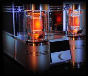
Yes, I've seen that. Lower voltage, custom switching power supplies, push-pull, I believe. I want the single-ended sound (primarily second order distortion), and I went with linear supplies because to design a good 2300V, 200 or so mA smps would be a monumental undertaking, beyond what I want to attempt at this time.
Nice looking amp, though. I intend to do something similar for the "containment vessel" around the 833.
Yes, I've seen that.
Audio Power Labs brings a semi trailer to the Dayton Hamfest every year with one of those in it. Last year I was too busy selling stuff to check it out, and this year will probably be the same. Two years ago I did check it out and talked with the designer. It is indeed a class A push pull mono block that makes about 200 watts. They only had one and it was connected to a pro audio speaker that looked like a stage monitor. It was set up inside a semi trailer with uncovered wood sides. LOUD, but not too great sounding.
A little more theory behind what I'm trying to do here...
I'm going with the ultra-high B+ voltage in order to keep the 833 in class A1 most of the time, and reduce the total amount of grid current needed. As I showed in a previous post, the amp will be in A1 up to 40W output, and the largest amount of grid current drawn is ~180mA at full power (195W).
A lot of the previous A2 designs here (the Koster Meteor, Bartola and ebozs variants on it, etc.) used lower voltage stacked power supplies in order to isolate the grid current demands from the voltage used as a reference for the 833 cathode. I'm doing quite the opposite, using the same supply for the driver stage and for the cathode and mosfet voltage references; in order for that to work, I need to isolate the cathode and mosfet reference voltages from the voltage drop caused by the grid current, and I plan to do that using shunt regulators, as outlined in the schematic in post #1.
I thus need to make the driver supply very robust and higher in voltage so that the voltage drop caused by grid current doesn't affect the reference voltages (247V and 220V for the 833 cathode and the mosfet, respectively). This is why the driver B+ supply is choke input at 400V with a transformer rated for 450V/300mA operation.
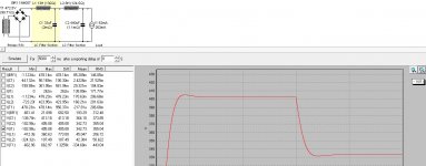
The attached PSUD shows what happens to the driver B+ when the current draw goes from 62mA (32 mA for the 6E5P and 30mA idle current for both regulators combined) to 262mA (assuming a worst case 200mA grid current draw). The driver B+ voltage stays above 330V, which is more than enough for the regulators to maintain their 247V and 220V levels. The gyrator on the 6E5P prevents the B+ drop from affecting that tube's operating points.
Anyone detect any flaws in this rationale?
.
I'm going with the ultra-high B+ voltage in order to keep the 833 in class A1 most of the time, and reduce the total amount of grid current needed. As I showed in a previous post, the amp will be in A1 up to 40W output, and the largest amount of grid current drawn is ~180mA at full power (195W).
A lot of the previous A2 designs here (the Koster Meteor, Bartola and ebozs variants on it, etc.) used lower voltage stacked power supplies in order to isolate the grid current demands from the voltage used as a reference for the 833 cathode. I'm doing quite the opposite, using the same supply for the driver stage and for the cathode and mosfet voltage references; in order for that to work, I need to isolate the cathode and mosfet reference voltages from the voltage drop caused by the grid current, and I plan to do that using shunt regulators, as outlined in the schematic in post #1.
I thus need to make the driver supply very robust and higher in voltage so that the voltage drop caused by grid current doesn't affect the reference voltages (247V and 220V for the 833 cathode and the mosfet, respectively). This is why the driver B+ supply is choke input at 400V with a transformer rated for 450V/300mA operation.
The attached PSUD shows what happens to the driver B+ when the current draw goes from 62mA (32 mA for the 6E5P and 30mA idle current for both regulators combined) to 262mA (assuming a worst case 200mA grid current draw). The driver B+ voltage stays above 330V, which is more than enough for the regulators to maintain their 247V and 220V levels. The gyrator on the 6E5P prevents the B+ drop from affecting that tube's operating points.
Anyone detect any flaws in this rationale?
.
Attachments
Last edited:
Hi Magz,
Very interesting. I guess the challenge is that the cathode needs stability and the gyrator supply needs less regulation so if the shunt supply is fed from same supply, you just need to ensure that the regulation of the shunt supply is very good to withstand the variance in the input voltage produced by the grid current pulses. Otherwise is easier to stack them")
BTW: if you have the 833 curves and grid current curves I can help you to develop a good SPICE model. I've done a very good one for 814 in class A2
let me know
cheers,
Ale
Very interesting. I guess the challenge is that the cathode needs stability and the gyrator supply needs less regulation so if the shunt supply is fed from same supply, you just need to ensure that the regulation of the shunt supply is very good to withstand the variance in the input voltage produced by the grid current pulses. Otherwise is easier to stack them
BTW: if you have the 833 curves and grid current curves I can help you to develop a good SPICE model. I've done a very good one for 814 in class A2
let me know
cheers,
Ale
Hi Magz,
Very interesting. I guess the challenge is that the cathode needs stability and the gyrator supply needs less regulation so if the shunt supply is fed from same supply, you just need to ensure that the regulation of the shunt supply is very good to withstand the variance in the input voltage produced by the grid current pulses. Otherwise is easier to stack them
BTW: if you have the 833 curves and grid current curves I can help you to develop a good SPICE model. I've done a very good one for 814 in class A2
let me know
cheers,
Ale
Thanks for the offer; I found a Spice model for the 833A on the Intact Audio Sim City site, and that's what I used for the Spice simulations in this thread. I assume that the 833C will be similar enough.
should be.Thanks for the offer; I found a Spice model for the 833A on the Intact Audio Sim City site, and that's what I used for the Spice simulations in this thread. I assume that the 833C will be similar enough.
tantalum vs graphite plate
So, I've been plugging along working up the sub-assemblies and laying them out on the chassis in order to determine where the holes should go. Making truly mirror-imaged monoblocks requires flexing a few more brain muscles since not only are the mounting positions mirror-imaged, but so are many of the sub-assemblies. For example, the layout of the rectifier board needs to be different for each mono if one desires to have the same spatial relationships and the shortest paths in each.
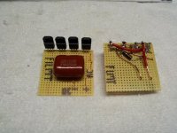
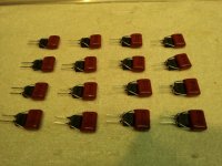
Below is a pic of the left and right filament rectifier boards, using 100V, 30A schottky diodes and a 330ohm-.022uF RC snubber network across the AC. These are designed so that the four diodes can be mounted using the back of the chassis as a heat sink; at 10A current even the filament rectifiers will produce a significant amount of heat! I left a little space in case I need to add a small first cap to adjust the voltage slightly.
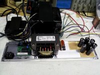
The second pic is of the back panel layout for the right mono, the left will be arranged in reverse. From L to R are the IEC inlet with integral fuse, the soft start board, the fuse holder for the filament supply fuse, the filament transformer (just fits on the back plate!) the filament rectifier board, a blank board where the HT rectifier board will be, and the first cap stage of the HT (7x150uF T-HA). The 833 and 6E5P transformers are shown in their intended locations on top of the chassis, and the first choke will be next to the big 733A transformer.
Below is a pic of the left and right filament rectifier boards, using 100V, 30A schottky diodes and a 330ohm-.022uF RC snubber network across the AC. These are designed so that the four diodes can be mounted using the back of the chassis as a heat sink; at 10A current even the filament rectifiers will produce a significant amount of heat! I left a little space in case I need to add a small first cap to adjust the voltage slightly.
The second pic is of the back panel layout for the right mono, the left will be arranged in reverse. From L to R are the IEC inlet with integral fuse, the soft start board, the fuse holder for the filament supply fuse, the filament transformer (just fits on the back plate!) the filament rectifier board, a blank board where the HT rectifier board will be, and the first cap stage of the HT (7x150uF T-HA). The 833 and 6E5P transformers are shown in their intended locations on top of the chassis, and the first choke will be next to the big 733A transformer.
Attachments
with such hi requirements filaments, i would go smps modules, they have pots for voltage adjustment
or even hack it ,and add slowstart circuit (often is used tl431 so it´s easy)

they have good filters at output, for peacemind can add another lc network--
----
fingers crossed, and want to see it working
or even hack it ,and add slowstart circuit (often is used tl431 so it´s easy)
they have good filters at output, for peacemind can add another lc network--
----
fingers crossed, and want to see it working
Switching supplies are another option; just not the option I ended up choosing this time.
Forgot to mention that the bottoms of the filament boards above are coated with a brush-on acrylic conformal coating (1500V dielectric strength per mil thickness) to help prevent any short circuits among the wiring should any wires move during assembly.
Forgot to mention that the bottoms of the filament boards above are coated with a brush-on acrylic conformal coating (1500V dielectric strength per mil thickness) to help prevent any short circuits among the wiring should any wires move during assembly.
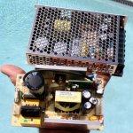
I just got these two from Digikey. The little one is 75 watts and will light the tubes in an amp I am working on. The big one is 100 watts and will power my first venture into the dark side (class D chip amp) in a long time. Tubes and battery power don't mix well at the 100 watt power level.
Attachments
- Home
- Amplifiers
- Tubes / Valves
- The Midlife Crisis - My 833C Amp Build