Why not use these instead of heavy iron? exists also types with active pfc

That was a possibility I considered. I even looked into a SMPS for the B+ (Ultravolt makes 2000VDC units, but I'd require 3 of them and they don't specify how much RF they emit - they would only tell me "some").
In the end, I decided to avoid the RF pollution issues and go linear PS.
Hey Magz, Fun project with a fitting name. Ive always liked this tube. I'm going to build an amp around it one day.
I think a 1 chassis design is frankly, a bad idea. That chassis would have to be very large and it would have to deal with all the iron bolted to it. It wouldn't be an off the shelf Hammond chassis. I think your setting your self up for disappointment by going this way. Plus a few trips to the doctor for your back.
If you proceed building this amp on one chassis all I can say is I hope you own a fork lift.
A power chassis and signal chassis is the best setup for a quite amp.
Nick
Hey Magz, Fun project with a fitting name. Ive always liked this tube. I'm going to build an amp around it one day.
I think a 1 chassis design is frankly, a bad idea. That chassis would have to be very large and it would have to deal with all the iron bolted to it. It wouldn't be an off the shelf Hammond chassis. I think your setting your self up for disappointment by going this way. Plus a few trips to the doctor for your back.
If you proceed building this amp on one chassis all I can say is I hope you own a fork lift.
A power chassis and signal chassis is the best setup for a quite amp.
Nick
It's actually two chassis, being monoblocks.
I'm aware of the limitations of putting the PS and signal in the same chassis; my 26 preamp is a 2-chassis unit for that reason. In this case, however, four chassis is just too much, since I have a 2-chassis linestage, a 2-chassis phonostage, and various other components...plus non-audio stuff
 . My plan is to keep the AC on one end of the chassis and the signal on the other, just as many other amps have been constructed over the years.
I'm not planning on using a flimsy Hammond chassis, I plan to use one of these:
http://www.diyaudio.com/forums/tubes-valves/229129-new-semi-custom-metal-chassis-manufacturer.html
On page six of the thread he drives over one with a truck...and he has guaranteed that if I'm not satisified with it I'll get a full refund. Can't beat that.
A power chassis and signal chassis is the best setup for a quite amp.
Nick
An umbilical carrying 2300VDC is decidedly unsafe. I'm doing my best to ensure that the ultra-HT stays inside one chassis. An amp is no fun if it kills you, your spouse or your dog.
sorry i meant filament supply onlyThat was a possibility I considered. I even looked into a SMPS for the B+ (Ultravolt makes 2000VDC units, but I'd require 3 of them and they don't specify how much RF they emit - they would only tell me "some").
In the end, I decided to avoid the RF pollution issues and go linear PS.
if you are worried about switching noise, i would add ferrite chokes and foil caps between smps and filaments. (still must add own slow rise circuit)
linear regs would add tons of heat
An umbilical carrying 2300VDC is decidedly unsafe. I'm doing my best to ensure that the ultra-HT stays inside one chassis. An amp is no fun if it kills you, your spouse or your dog.
It can be done safely. Thoughs landfall chassis a really pricey.
Nick
The inner conductor of RG-8 coax should be adequate for the HT. Also non-resistive spark plug wire. If you have to use an umbilical cord, you could use RG-8, put the plus down the center conductor and the ground return on the shield. The safest bet is to avoid the "umbilical cord" and keep all the voltages contained in one cabinet.
The inner conductor of RG-8 coax should be adequate for the HT. Also non-resistive spark plug wire. If you have to use an umbilical cord, you could use RG-8, put the plus down the center conductor and the ground return on the shield. The safest bet is to avoid the "umbilical cord" and keep all the voltages contained in one cabinet.
+ heavy duty copper sleeve over it, holding all together by nice heatshrink wrap
these are made in many sizes
An externally hosted image should be here but it was not working when we last tested it.
An umbilical carrying 2300VDC is decidedly unsafe. I'm doing my best to ensure that the ultra-HT stays inside one chassis. An amp is no fun if it kills you, your spouse or your dog.
If however, it kills your cat, that'd be great.
An umbilical carrying 2300VDC is decidedly unsafe.
We routinely have a 45kV umbilical in the lab. There is quite nice coaxial wire looking a bit like standard RG-59 but with a red outer insulation that is specified up to 30kV. The 45kV stuff is bit special, but only approx. 11mm in diameter and flexible like any other wiring.
Connectors are no problem either, just expensive. Lemo, Suhner, Fisher make nice HV connectors. A simple SHV connector is good up to 4kV as far as I remember.
Rundmaus
An umbilical carrying 2300VDC is decidedly unsafe.......It can be done safely.....We routinely have a 45kV umbilical in the lab.
It can be done. I used to maintain some laser systems that ran 25 KV at 1/2 Amp through the same umbilical that carried the cooling water. These laser systems ran 24/7 and failed often, sometimes quite spectacularly, but never because of the umbilical cable. Check out the X-ray machine in your dentist's office. That movable X-ray head that gets shoved right next to your face runs on 75 to 100 KV.
I built my 845SE on two seperate chassis, one power supply, and one stereo amp. The power supply is the smaller of the two, but the heaviest. I used test probe wire rated for 5 KV and ordinary Cinch-Jones plugs for the umbilical. Only 1100 volts though.....
Thoughs landfall chassis a really pricey.
Not when you consider the cost of the other parts. I am building an amp in a Landfall box. Why, because 40 pounds of 200 watt tube amp goes into a 3 RU box that will see some mechanical abuse. A thin Hammond or Bud box will bend under the pressure.....No, I won't park a truck on it, just put it into a portable guitar rig.
It can be done. I used to maintain some laser systems that ran 25 KV at 1/2 Amp through the same umbilical that carried the cooling water. These laser systems ran 24/7 and failed often, sometimes quite spectacularly, but never because of the umbilical cable. Check out the X-ray machine in your dentist's office. That movable X-ray head that gets shoved right next to your face runs on 75 to 100 KV.
I built my 845SE on two seperate chassis, one power supply, and one stereo amp. The power supply is the smaller of the two, but the heaviest. I used test probe wire rated for 5 KV and ordinary Cinch-Jones plugs for the umbilical. Only 1100 volts though.....
Yes, I agree it can be done, in the proper environment. I've worked in an analytical chemistry lab for the last 32 years, we have lots of very HV equipment such as mass spectrometers and inductively coupled plasma spectrometers, and in a lab environment where users are degreed professionals and there is no chance of children touching or dogs chewing or drunken party guests probing that is accepted practice. I however am not as comfortable having that type of voltage accessible in a home environment.
So...the HT will be in one box because that's what's safest and (secondarily) that's what will fit in the space allotted...it's my Midlife Crisis, after all
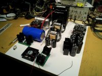
I've layed the components out on an 18"x22"piece of posterboard to see how they'll fit (see pic).
The filament trannie will go under the big 733A trannie (inside the box, bolted to the back plate) so it's not on the posterboard. The two white spaces are for the 833 B+ choke (back corner) and the OPT (front right corner). I think I might upsize slightly to 19"x23" for a bit more breathing room. Since the 369KX and 733A transformers, the 833 first choke and the OPT will be on top of the box I have a little more room than it looks.
Good thing I'm using the AOT1N60 driver setup in the schematic, there's no way I'd fit another stage of tubes and their associated peripherals in there, nor could I fit a bridge of 3B28s with their filament supplies for 833 B+. As it stands, the driver board will be fit into the white space near the tube socket and the rectifier boards will go along the side walls of the box.
The input from the preamp will come in on the left front side directly beneath the 6E5P tube socket. The output will exit on the right front side directly beneath the OPT. The left and right monoblocks will be mirror-imaged to achieve the shortest and most direct signal path from preamp to amp to speakers.
The fan shown will be located under the 833, which will be enclosed in a 6" OD pyrex glass tube with a vent cap on top.
This thing is about 80% power supply!
Attachments
Hi,
100% agreed!
Only crazy people create crazy projects.
@Magz: Good luck with your unbelievable project!
73
Wolfgang
Insanity indeed - but a good crazy!
100% agreed!
Only crazy people create crazy projects.
@Magz: Good luck with your unbelievable project!
73
Wolfgang
I've layed the components out on an 18"x22"piece of posterboard to see how they'll fit (see pic).
My rule of thumb, (sometimes painfully) learned from many electronics projects since I am able to hold a soldering iron: Plan the area needed for your layout carefully, then increase the estimated area by a factor of 1.5 to avoid problems that are difficult to solve later on...
Rundmaus
my Midlife Crisis, after all
Hey Magz, I'm right there with you. Sorry if I came across wrong.
Its a great project and I wish you the best for it.
One day I'll be building my own mid life crisis amp. Hopefully in my late thirties. Hey I'm impatient, Lol.
What will this beast be driving?
Nick
Sorry if I came across wrong.
No Sweat. I appreciate the interest and suggestions.
What will this beast be driving?
Nick
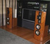
These Infinity RSIIb speakers, circa 1984.
They have been gutted and rebuilt by me with separate external crossovers in boxes behind the speakers, and new EMIM midrange diaphragms made by Apogee Acoustics in Australia. All wiring is Cardas copper Litz in Teflon.
They like power.
Attachments
Last edited:
No Sweat. I appreciate the interest and suggestions.
These Infinity RSIIb speakers, circa 1984.
They have been gutted and rebuilt by me with separate external crossovers in boxes behind the speakers, and new EMIM midrange diaphragms made by Apogee Acoustics in Australia. All wiring is Cardas copper Litz in Teflon.
They like power.
Very nice.
Keep us posted on your second mortgage, LOL.
Update: Just ordered two 18" x 22" x 4.25" chassis from Landfall in plain brushed aluminum finish. Once I have made all the appropriate holes and cutouts and tested things, I will disassemble and send them back to Landfall for finishing in the finish and color of my choosing.
I think that's a really nice service to be able to get the finishing done by the same vendor after I have cut it up - I don't need to worry as much about minor mishaps marring the finish in that way. Also, unlike Front Panel Express, the panels can then be anodized on the cut edges for a more finished look.
I think that's a really nice service to be able to get the finishing done by the same vendor after I have cut it up - I don't need to worry as much about minor mishaps marring the finish in that way. Also, unlike Front Panel Express, the panels can then be anodized on the cut edges for a more finished look.
- Home
- Amplifiers
- Tubes / Valves
- The Midlife Crisis - My 833C Amp Build