It has test points across it and is used to check the bias current. It may have some minor effect of optimizing the relative H2/H3 distortion profile. You could use a smaller value (2R2) just fine but may need to rebalance output node for 0v.
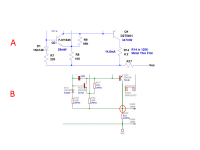
Thanks. I take it then that it's not critical whether it connects like "A," as in your first schematic, or like "B," as in the "JPS" schematic? Of course, beyond sensing a different current.