Very interesting. But saw form signal is not the most difficult signal for the amplifier. Try square signal.
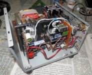
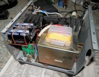
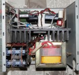
I've finaly made my amp. It happend I have different channels. There are KT 818/819 in one channel and TIP 41/42 in another one. But I hear no difference between them. And a heatsink is a little too small, although it is enough for home using.
mjf, what can you say about sound quality? Do you like how your amp plays music?
Attachments
I have had the same idea.
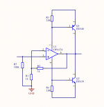
But here is a line amp using OPA134.
Up to like +/-20mA the op amp delivers the current.
Above this level the transistors will step in with current.
The result is a line amp with lots of driving capacity.
This amp will do well as a headphone amp.
But here is a line amp using OPA134.
Up to like +/-20mA the op amp delivers the current.
Above this level the transistors will step in with current.
The result is a line amp with lots of driving capacity.
This amp will do well as a headphone amp.
Attachments
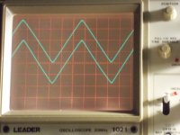
Very interesting. But saw form signal is not the most difficult signal for the amplifier. Try square signal.
mjf answer: a triangle is a "linear" signal, a straight line, so you can see deviations ("distortions") from it better on the screen ,e.g. a crossover distortion looks like a little shift in the mid of the signal.......
mjf, what can you say about sound quality? Do you like how your amp plays music?
in short: the sound is acceptable for me (if not i would throw it away.....).
i will carry on, tomorrow is a bank holiday here.........
Saw (triangle actually) makes it very easy to spot nonlinearities....
But saw form signal is not the most difficult signal for the amplifier.
...
Square makes it easy to spot "dirt" (oscillation) and transient behavior (slewing, rounding, spiking etc)
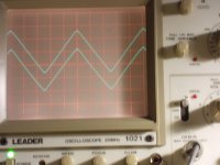
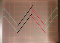
Am I imagining or is there a very slight kink in the curve where the boosters kick in (at 2.7R load) - which should be at around 3,5V. (IIRC you posted that you changed your sensing resistors to 0,5R and that would set the trigger current to somewhere at 1.2-1.4A, which would translate to cca. 3.5V into 2.7R).
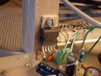
mjf, can I see a photo of your PCB? I am interested to see how you made the GND track.
it is only a prototype with an old pcb.........that means: a wire nest.
i will buy a tda2030a and other transistors soon.......
in short: the "- returns" are tied together in a single point.....and from this point a wire goes to the psu -
Attachments
- Home
- Amplifiers
- Chip Amps
- TDA2030 with transistors