LM1875 + Booster Transistors PCB
Oh wow that is awesome. Well if you do manage to build the circuit please let us know how it turns out.
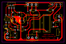
I have actually drawn a simple PCB on EasyEDA, you can find the project files in the below link. I have also attached an image of the PCB.
LM1875 + Booster Transistors - EasyEDA
Can it be, the God of DIY Audio is pointing with his Finger directly at me? The Things on the Photo are lying around here for about 3 Days.
Oh wow that is awesome. Well if you do manage to build the circuit please let us know how it turns out.
I have actually drawn a simple PCB on EasyEDA, you can find the project files in the below link. I have also attached an image of the PCB.
LM1875 + Booster Transistors - EasyEDA
Attachments
Hey charlbur many thanks for the Schematic! I'll give it a try in a few days, as soon as I got the Time. It looks all in all familiar, except R7. It's a 0 Ohm Resistor that appears only at the negative Voltage Rail. Should I know something about this?
Hi Clueless
Kay Pirinha was correct, it is simply a wire jumper for the PCB. EasyEDA doesn't have wire jumpers so you have to use a 0ohm resistor.
Best Regards
J.
Ok, I'm soldering right now. It will not be a very good looking circuit, because I've got only "recycled" parts (ca.90%) and a used experimental PCB. My soldering Iron is not the best suited for Electronics, and its made in a time when they made the IC's still out of wood ") .
.
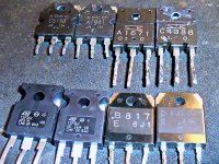
I've got a pair of TIP35/36C, but I also got some other Transistors which I recycled from different Amps.
I've got beside the TIP's a pair of 2SA1941/ 2SC5198, a pair of 2SA1671/ 2SC4386 and a couple of 2SB817/ 2SD1047.
I thought, maybe one of the other pairs could even be better suited for the task. What do you think?
.I've got a pair of TIP35/36C, but I also got some other Transistors which I recycled from different Amps.
I've got beside the TIP's a pair of 2SA1941/ 2SC5198, a pair of 2SA1671/ 2SC4386 and a couple of 2SB817/ 2SD1047.
I thought, maybe one of the other pairs could even be better suited for the task. What do you think?
Attachments
Hey Guys,
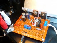
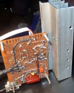
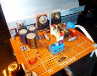
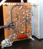
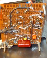
It's getting serious. I'm done with soldering (I hope so ), and I'm gonna fire this thing up soon. As Transistors I took the 2SB817/ 2SD1047 for the first try, so I won't kill the virgin TIP's right at the start.
Even the LM1875 is used, and I have no Idea if this Chip is still working. If not, I have got some unused as backup.
1st PSU will be about +/- 20V, I hope that is enough Voltage.
As I warned you, the Thing looks like an old shivering man did solder it, that could nearly be true. I'm turning 50 this year, and my soldering iron seems to be at the same age.
If you see something soldered wrong at the pics, feel free to tell me, but I think I'll have found that out by myself till then.
It's getting serious. I'm done with soldering (I hope so
), and I'm gonna fire this thing up soon. As Transistors I took the 2SB817/ 2SD1047 for the first try, so I won't kill the virgin TIP's right at the start.Even the LM1875 is used, and I have no Idea if this Chip is still working. If not, I have got some unused as backup.
1st PSU will be about +/- 20V, I hope that is enough Voltage.
As I warned you, the Thing looks like an old shivering man did solder it, that could nearly be true. I'm turning 50 this year, and my soldering iron seems to be at the same age.
If you see something soldered wrong at the pics, feel free to tell me, but I think I'll have found that out by myself till then
.Attachments
It is looking like you are making good progress. A 20-0-20 transformer should be okay or is the PSU ±20Vdc? If it is 20Vac it is getting very close to the LM1785 limit, 20Vac should rectify to about +28Vdc & -28Vdc which takes you to almost 60Vdc.
If your PSU is running at +20Vdc and -20Vdc you should get about 40W out of the amp.
Really looking forward to hearing how the testing is going? Cheers
If your PSU is running at +20Vdc and -20Vdc you should get about 40W out of the amp.
Really looking forward to hearing how the testing is going? Cheers
...looks like an old shivering man did solder it, that could nearly be true. I'm turning 50 this year, and my soldering iron seems to be at the same age.
I have a decade+ on you. Everybody gets unsteady at different times, but I could manage that project.
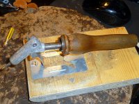
However that IRON looks more suited to a 1930s radio factory than most modern DIY. Save it for tractor-wiring (I had to solder a heavy 50 Amp bus for my large tractor) and get a nice 1970s+ 30-watt, or even one of these new (since the 1960s "soldering stations" with a straight end and a small chisel tip.
Hi there,
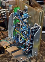
I'm sorry to disappoint you, but first I got to get my right speaker going as it should. The Tweeter Amp wasn't working, so I ... . Now all three Amps are quiet. Left side working ok, but right? One day it was working, but the next day it was dead and the cooler was pretty hot. After clueless screwing here, soldering there, I found out, one cable got lose from a rectifier and so the Amps got only one rail voltage, and seem to be dead.
EQ APO is also playing it's tricks on me, not to talk about the not only cheap, but really worthless 3,5mm mini jacks I ordered online.
For Sunday, there are two possibilities: I'm sitting in an mental hospital and getting used to wear a straightjacket as everydays Outfit, or my Speakers are ok now and I go on with the Transistor LM1875.
On the Photo, the Reason for my Mental Instability: "50 Shades of blue".
I'm sorry to disappoint you, but first I got to get my right speaker going as it should. The Tweeter Amp wasn't working, so I ... . Now all three Amps are quiet
. Left side working ok, but right? One day it was working, but the next day it was dead and the cooler was pretty hot. After clueless screwing here, soldering there, I found out, one cable got lose from a rectifier and so the Amps got only one rail voltage, and seem to be dead. EQ APO is also playing it's tricks on me, not to talk about the not only cheap, but really worthless 3,5mm mini jacks I ordered online.
For Sunday, there are two possibilities: I'm sitting in an mental hospital and getting used to wear a straightjacket as everydays Outfit, or my Speakers are ok now and I go on with the Transistor LM1875.
On the Photo, the Reason for my Mental Instability: "50 Shades of blue".
Attachments
Looks like you have been busy. I have had diodes smoke on me and let loose of the voltage rail on occasion. Be certain the rectifier is doing it's job and has not fizzled itself out before moving forward. Still looking forward to hearing about the single lm1875 with output transistors but it seems you have been quite involved with what appears to be an extensive build. May be 3 simple pcb's but it can be interesting what can go wrong when you start adding multiple components.
I bought the 2r7 resistors for the previous schematic and may assemble the circuit tonight for testing tomorrow. Hoping for positive results but I guess we just have to wait and see.
I bought the 2r7 resistors for the previous schematic and may assemble the circuit tonight for testing tomorrow. Hoping for positive results but I guess we just have to wait and see.
Okay so that run was a bust. Nothing fried but sounds like I get some faint tejano music and a 60 hz. hum. The chip alone output to the speaker without transistors get faint music from signal and hum. There is another thread using the tda7294 with output transistors that is extensive, I wonder if using the 6.8ohm SYNC resistors like in that post will produce better results. I suppose I will meander through that thread and compare schematics for another approach.
There are many configurations of this type of circuit using tda 2030, 2040, 2050, lm1875 etc. that connect output to emitters in some, collectors in others, and base in more. Looks like they all work on basically the same principal, with transistor taking on the load as voltage across the SYNC resistor exceeds .7 volts. I am still in pursuit of a stable and exceptional variation of this circuit with LM1875+TIP/to-3 transistors for increasing the output. I appreciate all the help here from all who have experience to share. Thanks!
There are many configurations of this type of circuit using tda 2030, 2040, 2050, lm1875 etc. that connect output to emitters in some, collectors in others, and base in more. Looks like they all work on basically the same principal, with transistor taking on the load as voltage across the SYNC resistor exceeds .7 volts. I am still in pursuit of a stable and exceptional variation of this circuit with LM1875+TIP/to-3 transistors for increasing the output. I appreciate all the help here from all who have experience to share. Thanks!
LM1875 + Booster Transistors Project
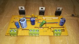
For those that might still be reading this post and are interested in building this amplifier, I have just completed a working prototype.
The prototype amp uses an LM1875 + TIP41/42C booster transistor. Most complementary pair transistors should work BD911/912, TIP35C/36C etc. The circuit was tested using a 23Vdc - 0 - 23Vdc power supply but it should be able to go up to at least a 28Vdc - 0 - 28Vdc PSU quite safely for best performance.
I have created and attached a schematic and component layout design on proto/stripboard using Fritzing. There is also a working LTspice simulation, with components, to see how the amp runs and performs with currents and voltages.
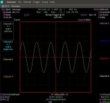
My test board seems to work very well and sounds pretty good, there is no noise, hum or audible distortion at all. I have also included an image showing my Xoscope output waveform which shows quite a nice clean output wave at almost full power.
I would like to thank Rod Elliot from Elliot Sound Products for his great article and valuable information on this subject which I used in putting the amp together, link below.
IC Power Amps
Enjoy and hope you come right.
For those that might still be reading this post and are interested in building this amplifier, I have just completed a working prototype.
The prototype amp uses an LM1875 + TIP41/42C booster transistor. Most complementary pair transistors should work BD911/912, TIP35C/36C etc. The circuit was tested using a 23Vdc - 0 - 23Vdc power supply but it should be able to go up to at least a 28Vdc - 0 - 28Vdc PSU quite safely for best performance.
I have created and attached a schematic and component layout design on proto/stripboard using Fritzing. There is also a working LTspice simulation, with components, to see how the amp runs and performs with currents and voltages.
My test board seems to work very well and sounds pretty good, there is no noise, hum or audible distortion at all. I have also included an image showing my Xoscope output waveform which shows quite a nice clean output wave at almost full power.
I would like to thank Rod Elliot from Elliot Sound Products for his great article and valuable information on this subject which I used in putting the amp together, link below.
IC Power Amps
Enjoy and hope you come right.
Attachments
-
 LM1875 + Booster BJT Proto Build.jpg171.2 KB · Views: 223
 -
 LM1875 + Booster BJT Layout rev1.0.png280.2 KB · Views: 209
 -
LM1875 + Booster BJT Layout rev1.0.pdf340.4 KB · Views: 77
-
LTspice - LM1875 + Booster BJT Simulation.zip139.6 KB · Views: 51
-
 LM1875 + Booster BJT Scope Output.jpg116 KB · Views: 236
Last edited:
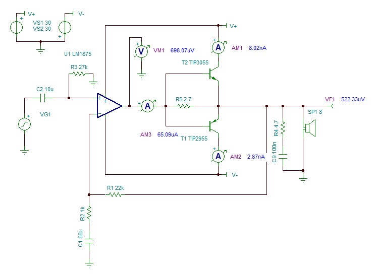
Not that bad, notice the 2.7 ohm resistor from chipamp out to speaker.
The first 250mA into load do NOT have crossover distortion by definition, they come from a properly designed chipamp, and above that booster transistors take over.
IF it not were present, but an open circuit, or too high value (1k? 10k?) yes, circuit would behave as you describe.
The first 250mA into load do NOT have crossover distortion by definition, they come from a properly designed chipamp, and above that booster transistors take over.
IF it not were present, but an open circuit, or too high value (1k? 10k?) yes, circuit would behave as you describe.
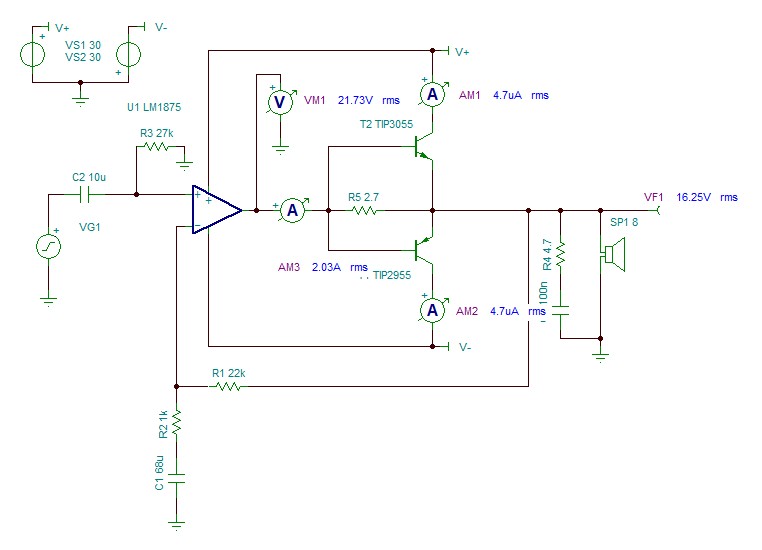
Doing basic DC analysis while bringing the amp up to 16.25 volts RMS
for 33 watts in 8R load
The chipamp shows 698 uV DC offset
The Transistors are basically off but the NPN sits slightly higher
NPN DC current is 8.02 nA ( off)
PNP DC current is 2.87nA ( off )
which is as expected
If you do AC Analysis
You will see what the 2.7 ohm resistor does.
True if the external transistors were actually on
the opamp signal would reduce crossover distortion.
Opamp output is 21.73 volts
but since there is a 2.7 ohm resistor in the way
Only 16.25 volts actually reaches the 8 ohm load. Basically 2 amps of current from the opamp.
Actually if the 2.7 ohm resistor was too high.
If you shorted the output of the amp. The opamp would not
go into protection.
But since its shorted DC offset shoots way up to 9 volts
So then the external output transistors would finally turn on. Well the NPN would turn on. And then blow up since the amp is shorted.
External transistor seem to be performing better than I expected.
Which is = Nothing
NPN 4.7uA AC current
PNP 4.7 uA AC current
as mentioned previously in the thread.
its better to use Darlington Output transistors
since it requires less current to turn them on. And also provide a bias network...so they actually turn on
Attachments
- Home
- Amplifiers
- Chip Amps
- TDA2030 with transistors