One leg of the cap onto a tweeter terminal, the other onto one of the resistor legs. The other resistor leg onto the other tweeter terminal.
Oh, like a Zobel network?
I actually tried that. 1uF and 10 ohms. It definitely smoothed things out, but went too far in the soft and mushy direction. Would be interesting to try that with 0.33uF and 50 or 100 ohms. I might get a chance to try that this weekend.
--
AllenB:
Originally Posted by strawberry
You are just guessing and presenting it as facts.
Go back and read my post. I called it an estimate and I brought its accuracy into question. I'm not sure I appreciate this kind of talk, strawberry.
phivates:
trash talk
Nor do I. This forum is for all of us who didn't get it the first hundred times, and without a range of responses, rather than the One and Only True Cure, we won't get our various, widely various, needs met. Just sayin
I, strawberry, was having an outburst against this:
AllenB:
What Michael has done here is the best estimative tool so far on the thread (and I was doing it behind the scenes as well), but a speaker is not resistive. This will be reasonably accurate in showing differences between two cases, but even less accurate at showing the absolute case, so the exact value is not really necessary.
By the way, the specs for this say the crossover is at 1k6Hz, for whatever that may mean.
strawberry: "What Michael has done here is the best estimative tool so far on the thread (and I was doing it behind the scenes as well)..." Best help so far? Not true. "the crossover is at 1k6Hz, for whatever that may mean" It just annoys me when some one who doesn't understand the problem is diminishing the better help of others (my help, in this case).
Anyway. Is the thread owner going to do anything about these speakers or did he give up at some point? What was the lasting alternation?
Also, is the inductor for the tweeter an iron core inductor? That is a problem, if so.
absolutely, yes, the worst
And if you have electrolytic capacitors for the tweeter, another huge downer.
not so much as one might think
that is, if they work at all
smooth foils are said to be quite good, actually
but smaller values
Strawberry. I may have created some confusion with that. My thinking at the time was that if I was going to call Michael's results inaccurate in any way, I wanted to recognise that he had spent valuable time working on it. After I wrote this I recognised that it had inadvertently ruffled a feather or two. That was not my intention. I considered setting it straight but these things can be tricky over a forum so I let it go.
I also criticised your suggested crossover but that was just business. I hadn't recalled you mentioning that you had modified this model yourself, and I disagreed with all the changes being carried out at the same time.
I also criticised your suggested crossover but that was just business. I hadn't recalled you mentioning that you had modified this model yourself, and I disagreed with all the changes being carried out at the same time.
I had this great big reply all typed up, but the connection timed out and I lost it. Argh!!
I had no idea my question would result in all this contention. My apologies.
The HP leg of the crossover has an air core inductor and mylar film caps. It's not that bad...
I've tried a bunch of things to tame the tweeters. I've put 50, 100 and 200 ohms in parallel to the tweeter. I've put a zobel (10 ohms, 1uF) on the tweeter. I've put a zobel (10 ohms, 22uF) on the woofer. I've put a 2 ohm resistor in series with the tweeter. All have had an effect. In the absence of a good test mic and SPL meter, I have nothing to go on past whether I like the change or not.
So I settled on the 200 ohm resistor in parallel to the tweeter, which mellows out the tweeter a hair, while not noticeably changing the frequency response in the crossover region. I also have a layer of poly batting stuck behind the grille cloth so that if I want to mellow the response out a bit more, I put on the grille. I know those are low-tech band-aid fixes, but they seem to work pretty well.
I intend to take a couple of pieces of hardboard and wire up a different crossover following strawberry's suggestions. I'm sure it will sound very different. I think the Klipsch engineers compensated for irregularities in the response of the drivers. The tweeter probably has a falling response with rising frequency, and the woofer probably needed a boost around 800 HZ to compensate. If that's the case, a different crossover will sound very, very different. Better? I'd like to find out...
But... All this experimenting with floorstanding speakers elicited a complaint from my downstairs neighbors. So now, instead of fun with speakers, I'm researching soundproofing. Just got a sheet of mass loaded vinyl and have to go pick up a new area rug. Next up will probably be a second layer of sheetrock on the wall behind the speakers. Sounds like a blast, right?
At any rate, thank you all for your input. I certainly have learned a lot from these guided experiments, and I understand at least some concepts of filter design better than I did before. Many thanks....
--
Sounds good. It's probably a good guess that 10uF on the tweeter will sound the best, along my previous recommendation. Whatever value you settle with for the tweeter, 5.5uF perhaps, put the same value across the connectors of the woofer, separate but alongside the whole Zobel of 10 ohm and 22uF or 33uF. This will ensure a smooth phase shift, which means cleaner sound. You are almost there, the ultimate sound.
Good grief, 11 pages of floundering with this harsh sounding Klipsch Horn...
Lets just disregard everybody's valuable meanderings and just do this properly!
Here's the TERRIBLE cheap Klipsch circuit from post #10:
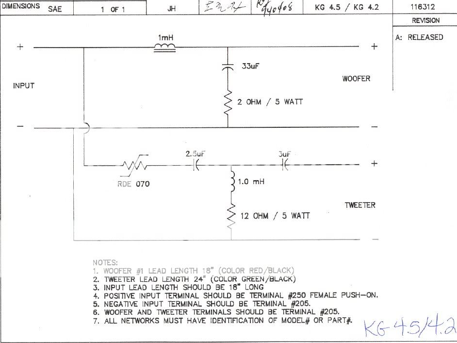
Bad at so many levels. Mainly that at high attenuation it loads the horn with a high source impedance, which will sound HARSH and exaggerrate high frequencies!
The better standard design is this:
The Horn never sees worse than 8 ohm source impedance even in the stop band, which helps damping and smoothness. At high attenuation it is much less. The Zobel Network does what it does best in keeping frequency response constant for varying source impedance. The potentiometer is a more expensive unit that handles higher power, but is really best replaced with a pad for 8 ohms load, once the level setting to match the woofer is decided. The original 3rd. order Klipsch design filter is a terrible botch, and best replaced with a Properly calculated one for 8 ohms.
A properly designed high efficiency horn can work very well, but notice that an attenuator IS used in the filter here:
tractrix-bms-4524 - YouTube
Lets just disregard everybody's valuable meanderings and just do this properly!
Here's the TERRIBLE cheap Klipsch circuit from post #10:
Bad at so many levels. Mainly that at high attenuation it loads the horn with a high source impedance, which will sound HARSH and exaggerrate high frequencies!
The better standard design is this:
An externally hosted image should be here but it was not working when we last tested it.
The Horn never sees worse than 8 ohm source impedance even in the stop band, which helps damping and smoothness. At high attenuation it is much less. The Zobel Network does what it does best in keeping frequency response constant for varying source impedance. The potentiometer is a more expensive unit that handles higher power, but is really best replaced with a pad for 8 ohms load, once the level setting to match the woofer is decided. The original 3rd. order Klipsch design filter is a terrible botch, and best replaced with a Properly calculated one for 8 ohms.
A properly designed high efficiency horn can work very well, but notice that an attenuator IS used in the filter here:
tractrix-bms-4524 - YouTube
system7, excellent idea. I wonder why I had that mental blockage to not see it myself. If a Zobel circuit tames harshness in a woofer, it should work on a tweeter too. Up until now I have seen L-pads as the only way to attenuate top end, but a Zobel circuit attenuates and removes harshness at the same time, clearly the better choice. I'm in the process of applying Zobel circuits to my own living room speakers which I have been slightly unhappy about, regarding the rise and harshness at the top end. For me it's going to be 0.82uF and a 5 ohm resistor, closest to the tweeter connectors.
The thread owner should absolutely add a Zobel circuit, 0.47uf-1uF and 5-10 ohm, to what ever crossover there will be. Pick a resistor 1 ohm larger than the DC resistance of the tweeter.
The thread owner should absolutely add a Zobel circuit, 0.47uf-1uF and 5-10 ohm, to what ever crossover there will be. Pick a resistor 1 ohm larger than the DC resistance of the tweeter.
I had that mental blockage to not see it myself. If a Zobel circuit tames harshness in a woofer, it should work on a tweeter too.
Wow - that's a real revolation! I don't know how I could have missed it all these years.
hmm, if the zobel is the last 'curcuit' placed before the tweeter, it would affect the attenuation placed before it, yes ?
and if a horn tweeter appears difficult to attenuate, or the attenuation isnt working like it should, the zobel might actually help on that, no ?
but a magical cure its not, just logic I presume
and if a horn tweeter appears difficult to attenuate, or the attenuation isnt working like it should, the zobel might actually help on that, no ?
but a magical cure its not, just logic I presume
What a calculated Zobel also does is flatten the impedance seen by the source or amplifier. Normally a 6.2 ohm tweeter like mine adds a 0.05mH inductive component. 7.75 ohm plus 0.832uF Zobel flattens it to a constant 6.2 ohms:
You will see a fly in the ointment at the point that 0.05mh inductance series RLC resonates with the 0.832uF Zobel capacitance through the 13.95R resistance, especially if driven by high impedance source. I made inverse root LC to come out at about 30Khz with a lowish Q.
So it looks like a Zobel tames a rising tweeter inductance in return for a RLC resonance above the audio band, which might annoy bats and dogs a bit!
I haven't done the maths too exactly, and it's surely not hard, but it looks BENIGN really. Good voltage amps can drive a moderate reactance OK. Your own mileage might vary with higher tweeter inductance and lower Re (say 4 ohm) resistance which might be problematic.
An externally hosted image should be here but it was not working when we last tested it.
You will see a fly in the ointment at the point that 0.05mh inductance series RLC resonates with the 0.832uF Zobel capacitance through the 13.95R resistance, especially if driven by high impedance source. I made inverse root LC to come out at about 30Khz with a lowish Q.
An externally hosted image should be here but it was not working when we last tested it.
So it looks like a Zobel tames a rising tweeter inductance in return for a RLC resonance above the audio band, which might annoy bats and dogs a bit!
I haven't done the maths too exactly, and it's surely not hard, but it looks BENIGN really. Good voltage amps can drive a moderate reactance OK. Your own mileage might vary with higher tweeter inductance and lower Re (say 4 ohm) resistance which might be problematic.
Last edited:
Try 6.2 ohms and 1u3F.You will see a fly in the ointment at the point that 0.05mh inductance series RLC resonates with the 0.832uF Zobel capacitance through the 13.95R resistance
What's good about THAT then?Try 6.2 ohms and 1u3F.
Sounds like one of those engineering tradeoffs that makes something better while making something else worse!
Guess your circuit calculator is called for AllenB. Lots of variables to play with. Source impedance, resistive pads and even notch filters, I'd guess. Looks to me like tweeter inductance Le and resistance Re involve some tradeoffs too. Interesting. Increase the tweeter resistance and you push the Zobel resonance higher. The Q stays around 1. Maybe you just tailor frequency response of the source not to aggravate it. CD source usually rolls off below 22kHz IIRC.
- Status
- This old topic is closed. If you want to reopen this topic, contact a moderator using the "Report Post" button.
- Home
- Loudspeakers
- Multi-Way
- Taming harshness in horn tweeter