Gentlemen - having "tamed harshness in a horn tweeter", a Zobel has nothing to do with it.
You're probably right. Better to design a non-harsh tweeter in the first place. But I have this problem... A Klipsch speaker with a "hot" treble. So I'm trying to tame it to the point that I can live with the speaker. Actually, I've already done that, well enough for me. Now it's in the realm of "what's the best way to modify (or re-design) this crossover to tame the tweeter harshness?"
To that end...
Like this?
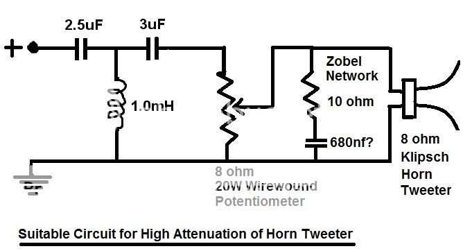
Or do the L and C values in the HP network need to be changed too?
Without some measurments its all just guessing. Usually these kinds of horns have strong peaks which must be "tamed", but without knowing where tose are its a crap-shoot. A Zobel will do nothing to a peak in the response. And usually a 3rd order HP is not required. Horn have a natural HP function.
gedlee, put Zobles on your own woofers and tweeters and you will see what I'm talking about. The sound changes character. The sound is not longer coming from a stone grinder. I think the amp has a less strained work load and so it is working easier. That's all I can say. My ears don't lie. It's not just about a roll off of power. You can argue all you want. I'm not removing the Zobels.
If anything, I've oversimplified the matter but I thought you might like to see anyway.What's good about THAT then?
Sounds like one of those engineering tradeoffs that makes something better while making something else worse!
Well, I believe you like the difference. As Dr. Geddes suggests, I suspect you've rolled off the top end.My ears don't lie.
The RC circuit you've added to create this frequency response change is not a Zobel, but that's OK if it works for you. Zobels do not actually fix harshness and furthermore, adding Zobel correction to a preexisting crossover is technically wrong.
Attachments
Most people I think assume that a zobel on a tweeter will do nothing (since it's flattening the impedance well above the high pass crossover frequency) but in actual fact it can still roll off the top end of a pre-existing tweeter crossover quite a lot.Well, I believe you like the difference. As Dr. Geddes suggests, I suspect you've rolled off the top end.
As an example I have a ribbon tweeter with a passive 4Khz 18dB/oct butterworth crossover, the tweeter has a very modest impedance rise at the top end compared to a dome (rising from a minimum of 8 ohms at 3Khz to only 9 ohms by 20Khz) yet connecting a zobel to flatten out the impedance curve causes a full 1dB reduction of high end treble above around 7-8Khz, as well as a significant change in the response shape from 4-10Khz. (Without the zobel the crossover actually has voltage "gain" at high frequencies of nearly 1dB...) A 1dB reduction in top end treble is a very noticeable change.
On the other hand all the zobel is doing is rolling off the high end, it's not curing any harshness, perhaps just making it less noticeable in the same way the same EQ applied elsewhere would. (It's still there though, if you listen to the right music)
The RC circuit you've added to create this frequency response change is not a Zobel, but that's OK if it works for you. Zobels do not actually fix harshness and furthermore, adding Zobel correction to a preexisting crossover is technically wrong.
Exactly. If a zobel gives you the target response, fine. If you can get the target response without it, also fine. Just adding it to a crossover not optimized to have it or removing it from one that was optimised with one in mind is just pot luck though.
I think Earl summed up "harshness" quite well in another thread - "a lack of high frequency response smoothness". In other words one or more steep narrowband frequency response variations are usually the culprit. If the high frequency response measured with a narrow band analyser is very smooth with only low slope gradual variations it should not sound harsh. A zobel will only ever make gradual changes to the response and therefore can do nothing for narrow band peaks and dips that might cause harshness.
Last edited:
Would anyone like to help me understand this better? For an example, I have a pair of Tangband drivers, complete with the factory specsheet. I'm sure the published specs are pretty far from the actual characteristics of the drivers, but I can't do much about that. But at least I have some specs to start with, instead of the Klipsch with none at all.
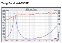
I've attached the published curves for the Tangband W4-930SF. It has a rising response, including a rising impedance as you go up in frequency.
This speaker has a pretty good spike at 6500 Hz or so. It sounds like it, too. Also a pretty intense flip at about 13kHz, but let's say we leave that alone for now.
First, would a zobel be the first thing to apply, to make the impedance appear flatter to any notch filters, etc. you'd apply?
After that, what nominal impedance would you choose for figuring LCR values for a notch filter? 6 ohms, or the voice coil DCR of 5.6 ohms? Or the impedance at the frequency to be notched?
The T/S parameters from the spec sheet:
Nominal Z = 6 ohms
DCR = 5.6 ohms
Le = 0.15mH
Sensitivity = 89dB/1w/1m
Free air resonance = 70 Hz
Qts = 0.47
Qms = 4.32
Vas = 8.72 liters
Thanks.
--
PS - I have found the formulae for choosing RLC values for a notch filter, but applying that to a real driver is always more complicated. That's why I'm asking... Thanks again.
Attachments
Last edited:
On first thoughts I wouldn't add impedance rise compensation just to notch the 6k5 peak because roughly speaking, the notching effect is somewhat narrowband and kind of takes care of itself, but more on that in a minute.
I probably would add full Zobel compensation before I started a fresh crossover for no reason other than it allows a more free flow of ideas during design. Later I'd probably try to squeeze it out.
A hint on notching the peak though. I'd try to figure in a small dip in the sensitive 3k-4k5 regions with the same notch filter as the 6k5, trying to flatten one edge of it with the edge of the filter. I'm only guessing whether it would work at this stage and it may not, but in balancing up those two tasks here, the impedance rise might have an influence on that balance and that would be a reason to look at modifying the impedance at that node.
I hope that was helpful.
For the Zobel, I got 3uF for C and 7 ohms for R.
Next up, figuring the notch filter. So Allen, you'd make a broad filter that would attenuate the 3k to 4.5kHz region? The equations I've seen for calculating the notch filter components ask for a F3lo and an F3hi, with the peak in the center. Are you thinking the center should be lower than 6.5kHz, and the filter should be broad acting (low Q)?
Trying to understand what you wrote, I hope I'm close.
--
Yes, that's what I'm suggesting.
Let me make it clear though, attenuating this region is optional. It is arguably incorrect. However, it is about as common and as well accepted as people suggesting that they'll boost their bass by a dB or two. That said, I wouldn't normally go beyond a few dB here, i think you should keep it subtle, simply take advantage of the opportunity.
Let me make it clear though, attenuating this region is optional. It is arguably incorrect. However, it is about as common and as well accepted as people suggesting that they'll boost their bass by a dB or two. That said, I wouldn't normally go beyond a few dB here, i think you should keep it subtle, simply take advantage of the opportunity.
The Great Capacitor Shoot-Out
High End Audio - Electrolytic capacitors
The "Sound" of Capacitors
I have a variety of capacitors to build crossovers from and different capacitors give a different sound. I guess some of you feel better about pretending this can't possibly be true.
High End Audio - Electrolytic capacitors
The "Sound" of Capacitors
I have a variety of capacitors to build crossovers from and different capacitors give a different sound. I guess some of you feel better about pretending this can't possibly be true.

@AllenB. Great plots of phase and amplitude response there, my friend. Very interesting. Also, FWIW, based on a misunderstanding. My guesstimate of Zobel correction is probably better than yours, because a Zobel 1.25 fudge factor on the resistor value actually accounts for a LOSSY voice coil. The fact is that speaker impedance doesn't rise at 6dB per octave, but closer to 4-5dB. The magnet gap affects it.
Good progress on this big, loud and coloured Klipsch KG4.5:
The horn looks like it has the usual compression driver 1" dome, probably Le around 0.05mH, available as replacement unit:
Klipsch Replacement Speaker Diaphragm K75, K76, K78, K79, D-417,
I misunderstood the circuit. What I thought was an attenuator at the input was a fuse, but no matter. I have dug up a selection of weird Klipsch crossovers for various models:
<meta name="description" content="Klipsch audio systems provide the true audio/video lover a wide variety of high performance loudspeakers and loudspeaker systems for music and home theater entertainment centers, including iPod speakers, multimedia s
Later models used a purely reactive 3rd. order tweeter crossover at around 2-3 KHz. This means the 12R/1mH gets changed to about 0.25mH and that 3uF could probably change to around 8uF. The 2R resistor in the 33uF/2R shunt at the bass end could probably just go too. Can't imagine what it does, it's not a Zobel for sure.
Some models put a 40R resistor across the horn. All a bit of a fudge. I expect these speakers would have sounded much better with valve amps and Klipsch are probably struggling to get it right with a solid-state. Biggish horns always shout a bit in the midrange, and fall away at the very top, it's their nature.
Maybe a bit stupid to try and treat this beast as a HiFi speaker, but Rod Elliot explains how Zobels and notches are used properly here:
Passive Crossover Network Design
Good progress on this big, loud and coloured Klipsch KG4.5:
An externally hosted image should be here but it was not working when we last tested it.
The horn looks like it has the usual compression driver 1" dome, probably Le around 0.05mH, available as replacement unit:
Klipsch Replacement Speaker Diaphragm K75, K76, K78, K79, D-417,
I misunderstood the circuit. What I thought was an attenuator at the input was a fuse, but no matter. I have dug up a selection of weird Klipsch crossovers for various models:
<meta name="description" content="Klipsch audio systems provide the true audio/video lover a wide variety of high performance loudspeakers and loudspeaker systems for music and home theater entertainment centers, including iPod speakers, multimedia s
Later models used a purely reactive 3rd. order tweeter crossover at around 2-3 KHz. This means the 12R/1mH gets changed to about 0.25mH and that 3uF could probably change to around 8uF. The 2R resistor in the 33uF/2R shunt at the bass end could probably just go too. Can't imagine what it does, it's not a Zobel for sure.
Some models put a 40R resistor across the horn. All a bit of a fudge. I expect these speakers would have sounded much better with valve amps and Klipsch are probably struggling to get it right with a solid-state. Biggish horns always shout a bit in the midrange, and fall away at the very top, it's their nature.
Maybe a bit stupid to try and treat this beast as a HiFi speaker, but Rod Elliot explains how Zobels and notches are used properly here:
Passive Crossover Network Design
That peak at 6.5KHz is a textbook example of a resonance that would add harshness, (perhaps sibilance too, given its frequency) and because its symmetrical in shape and the response is relatively flat on either side, is a good candidate for correction with a notch filter, be it passive or active.I've attached the published curves for the Tangband W4-930SF. It has a rising response, including a rising impedance as you go up in frequency.
This speaker has a pretty good spike at 6500 Hz or so. It sounds like it, too. Also a pretty intense flip at about 13kHz, but let's say we leave that alone for now.
The resonances in the 15Khz region may be audible as a slight hard edge as well, although with a full range driver 15Khz will be very directional so it probably wouldn't be nearly as noticeable as the one at 6.5Khz. (It's also close to the high frequency limits of hearing)
If you have access to an active parametric EQ then it would be very helpful to try accurately correcting the peak at 6.5Khz (and perhaps the ones at 15Khz as well) to see what it sounds like before going to the trouble of building passive notches. A few seconds of twiddling the knobs on a PEQ and 10 minutes listening will let you know if you're on the right track or not.
I probably would start with a zobel to flatten the impedance, yes. A flat impedance will result in a symmetrical notch using an RLC notch, whereas a rising impedance would cause an asymmetric notch.First, would a zobel be the first thing to apply, to make the impedance appear flatter to any notch filters, etc. you'd apply?
Impedance at the frequency to be notched.After that, what nominal impedance would you choose for figuring LCR values for a notch filter? 6 ohms, or the voice coil DCR of 5.6 ohms? Or the impedance at the frequency to be notched?
However its easy to get carried away with trying to calculate these things to the nth degree when its really not necessary. Do a rough calculation, measure, tweak. You'll need to be measuring the response of the driver anyway, which wont be quite as published. For a notch filter correcting a high Q resonance its really important for the centre frequency to be correct or you can just make things worse. (You end up with two side by side resonances instead of one cancelling the other out)
The way I like to do it is measure the acoustic response, use a digital active PEQ to adjust the centre frequency, width, and depth to give the flattest measured response, measure the electrical response at the speaker terminals with the PEQ in place - then build a passive notch that follows that electrical response (with the PEQ turned off) as closely as possible.
")
Not to contradict AllenB, but IMHO you shouldn't be attempting to correct two different and widely spaced resonances with one notch filter. If you make a notch that is broad enough to encompass both the 6.5Khz resonance and the small bump around 3.5Khz then it won't correct either of them properly.Next up, figuring the notch filter. So Allen, you'd make a broad filter that would attenuate the 3k to 4.5kHz region? The equations I've seen for calculating the notch filter components ask for a F3lo and an F3hi, with the peak in the center. Are you thinking the center should be lower than 6.5kHz, and the filter should be broad acting (low Q)?
Trying to understand what you wrote, I hope I'm close.
--
Sure, it might drop the level of them both a bit, making them a bit less annoying, but much like a zobel it won't cure the harshness. The only way to cure the harshness that the 6.5Khz resonance might introduce is to precisely and exactly correct it - which means the centre frequency, Q/bandwidth and depth must match the resonance exactly.
If you correct a narrow high Q resonance with a wide low Q notch filter it will not correct the ringing in the time domain, and will also cause a dip on either side of what used to be the peak. If there are two independent resonances it takes two independently tuned notch filters to correct them in such a way that harshness will be removed.
To be honest the peak at 3.5Khz looks fairly benign, but if you do try to correct it, use a separate notch filter.
As I said if you have access to a multi-band active PEQ with fully variable centre frequency, Q/bandwidth, and depth, you can very quickly evaluate the subjective improvement of correcting one or more driver resonances.
Last edited:
And perhaps power is beginning to drop anyway at that point regardless of the on-axis rise.To be honest the peak at 3.5Khz looks fairly benign,
My suggestion was stretching things with a compromise penalty. Probably best to pass on it.
Once again you guys have been most helpful. Many thanks for this.
The discussion on the Tangband and that notch did help. I guess it comes down to having decent measuring equipment to verify that you haven't actually made things worse. I didn't have any idea of what might happen if you "miss" the target frequency to be notched out, and the Q of the filter.
You know, I could have borrowed a couple of different EQs, one a graphic, the other a parametric 3-band. Oh well, I think that window of opportunity has closed.
Now, back to the Klipsch beastie.
system7, that was an interesting discussion on how Klipsch crossover designs changed through the years.
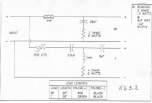
Interesting coincidence too that I bought a spare pair of KG4.5 crossovers on eBay (the price was right). They say KG4.5 on them, plain as day, but they are not the same as the crossovers in the speakers I have. These eBay-bought crossovers look exactly like the crossovers for KG5.2. The woofer circuit is the same (1mH, 33uF 2nd order with that 2 ohm resistor between the 33uF cap and ground). . The tweeter circuit is a bit different, though. The cap values are changed to 2.5uF and 8uF, and the 12 ohm resistor from the 1mH inductor to ground is changed to only 4 ohms. I should try popping that crossover in and seeing if it makes a big difference. The KG5.2 used the exact same tweeter and woofer as the KG4.5, but instead of a vented cabinet. or a 10" passive radiator in the case of the KG4.2, the 5.2 used a 12" passive radiator. I guess that answers the question -- I should try the different (later version) crossover.
Does that KG5.2 crossover look less obviously weird than the original KG4.5 crossover? Or just as bad, only different?
I'll also try connecting the 33uF directly to ground by shorting out that 2 ohm resistor, and try to see if I can hear the difference.
Hah! I did that. It does cool out the tweeter, quite noticeably. But I thought it also closed down the speaker, made it lose the character that was fun about this speaker. Might be that the only thing attractive about this speaker is that it's loud and brash like a PA speaker. BTW, the Chorus and Forte models that have this 40 ohm parallel resistor are 3-ways, using a different tweeter driver.
--
The discussion on the Tangband and that notch did help. I guess it comes down to having decent measuring equipment to verify that you haven't actually made things worse. I didn't have any idea of what might happen if you "miss" the target frequency to be notched out, and the Q of the filter.
You know, I could have borrowed a couple of different EQs, one a graphic, the other a parametric 3-band. Oh well, I think that window of opportunity has closed.
Now, back to the Klipsch beastie.
system7, that was an interesting discussion on how Klipsch crossover designs changed through the years.
Interesting coincidence too that I bought a spare pair of KG4.5 crossovers on eBay (the price was right). They say KG4.5 on them, plain as day, but they are not the same as the crossovers in the speakers I have. These eBay-bought crossovers look exactly like the crossovers for KG5.2. The woofer circuit is the same (1mH, 33uF 2nd order with that 2 ohm resistor between the 33uF cap and ground). . The tweeter circuit is a bit different, though. The cap values are changed to 2.5uF and 8uF, and the 12 ohm resistor from the 1mH inductor to ground is changed to only 4 ohms. I should try popping that crossover in and seeing if it makes a big difference. The KG5.2 used the exact same tweeter and woofer as the KG4.5, but instead of a vented cabinet. or a 10" passive radiator in the case of the KG4.2, the 5.2 used a 12" passive radiator. I guess that answers the question -- I should try the different (later version) crossover.
Does that KG5.2 crossover look less obviously weird than the original KG4.5 crossover? Or just as bad, only different?
I'll also try connecting the 33uF directly to ground by shorting out that 2 ohm resistor, and try to see if I can hear the difference.
Some models put a 40R resistor across the horn.
Hah! I did that. It does cool out the tweeter, quite noticeably. But I thought it also closed down the speaker, made it lose the character that was fun about this speaker. Might be that the only thing attractive about this speaker is that it's loud and brash like a PA speaker. BTW, the Chorus and Forte models that have this 40 ohm parallel resistor are 3-ways, using a different tweeter driver.
--
Attachments
Last edited:
- Status
- This old topic is closed. If you want to reopen this topic, contact a moderator using the "Report Post" button.
- Home
- Loudspeakers
- Multi-Way
- Taming harshness in horn tweeter