It really looks to me like a slight pad on the horn is the way forwards, after fitting a Zobel. I suspect any tonal changes will just have to be regarded as a tradeoff, because there isn't any level to play with if it's to match the woofer.
Of course, you do get a lot of harshness from woofers that are getting out of their best range. I need to work at my own woofer in this respect.
This is an 18" designed to crossover at 800Hz. You can see that without a Zobel, the gentle 2nd. order linkwitz-riley is struggling in curve b. Things get better after impedance correction, curve a. Taken from an old Marshall Leach paper.
Edit:
That IS a more normal looking crossover for a voltage amp. 3rd order Crossovers for valve amps are more symetrical because of the (4R?) source impedance. That 1mh /4R shunt is some sort of attempt to lift high frequencies. I think there are better ways to do that.
Of course, you do get a lot of harshness from woofers that are getting out of their best range. I need to work at my own woofer in this respect.
An externally hosted image should be here but it was not working when we last tested it.
This is an 18" designed to crossover at 800Hz. You can see that without a Zobel, the gentle 2nd. order linkwitz-riley is struggling in curve b. Things get better after impedance correction, curve a. Taken from an old Marshall Leach paper.
Edit:
That IS a more normal looking crossover for a voltage amp. 3rd order Crossovers for valve amps are more symetrical because of the (4R?) source impedance. That 1mh /4R shunt is some sort of attempt to lift high frequencies. I think there are better ways to do that.
Last edited:
It really looks to me like a slight pad on the horn is the way forwards, after fitting a Zobel.
OK. Zobel values 0.47uF and 10 ohms.
What attenuation to go for with the L-pad? How about Rs = 1R, Rp = 50R? That should give just a hair over -1dB.
Edit:
That IS a more normal looking crossover for a voltage amp. 3rd order Crossovers for valve amps are more symetrical because of the (4R?) source impedance. That 1mh /4R shunt is some sort of attempt to lift high frequencies. I think there are better ways to do that.
Ah, that's good to know. What better way to lift high frequencies? A series resistor? But wouldn't that conflict with the L-pad? Or ditch the L-pad, try a series resistor instead of the resistor below the 1mH to ground?
--
@AllenB....Also, FWIW, based on a misunderstanding.
Oversimplified, as stated, and not just the single pole shown. But I guess if there was any point I'd like to make out of it, it's that correction can be a compromise at the best of times and depending on what the goal is, I sometimes move toward a higher capacitance than formulas suggest.
For what it's worth, Here are the results of two online impedance rise compensation calculators. The first is based on the drivers nominal impedance and the frequency where it doubles, the other is based on Re and Lvc. Zphase is shown dotted.
Attachments
my own woofer......without a Zobel, the gentle 2nd. order linkwitz-riley is struggling
Just for others here and to illustrate what Simon said earlier, the correction is one way forward, but there are other ways.
I've created a second order rolloff by starting with RC impedance correction, then a text-book filter (first plot).
Then taken the Zobel away (second plot).
Then modified the circuit to make it work again. The RC in the third plot is not Zobel correction.
Attachments
You do interesting stuff with that circuit simulator, AllenB. Of course your fudged last Klipsch-style circuit probably does horrible things to load impedance. 
Seems to me these Zobels are worth persevering with. They don't do anything unpleasant to impedance if you get reasonably close. Makes it better actually. Can't go wrong if you start with a small capacitor and 10 ohms.
FWIW, I just reminded myself what the L-pad values are for 8 ohm load:
Attenuation in dB, R1 in Ohms, R2 in Ohms
1, 0.87, 65.56
2, 1.65, 30.90
3, 2.34, 19.39
4, 2.95, 13.68
5, 3.50, 10.28
6, 4.00, 8.00
7, 4.43, 6.46
8, 4.82, 5.29
9, 5.16, 4.40
10, 5.47, 3.70
11, 5.75, 3.14
12, 5.99, 2.68
I think you usually go for 10W wirewound on bass units where they are getting some real power. This goes for Zobels too. IIRC, bass units usually have Le from 0.15mh to a max of 2mH on huge PA drivers. Tweeter Le is uncannily usually between a standard 0.05mH and 0.09mH on the more exotic.
Last edited:
Oh yes. Purple (Zobel) is DEFINITELY best!Well thank you system7, I think
and since you mentioned it, Red is the raw speaker, Black is my 'fudge', Purple is the textbook filter with, and Blue without the impedance correction.
OK, Ive been looking at some filters that will use those two 1mH inductors.
An externally hosted image should be here but it was not working when we last tested it.
So far I've got a second order Linkwitz-Riley at 2.5 KHz and 8 ohm which needs 1mH and 4uF in both legs. Tweeter Zobel 680nF and 10 ohms (5W W/W). Bass zobel is a guess, but 10 ohm (10W W/W) and 8uF (15uF?) would be a start. Attenuators to taste, probably not more than 2dB.
What do you think?
Last edited:
Great example.Just for others here and to illustrate what Simon said earlier, the correction is one way forward, but there are other ways.
I've created a second order rolloff by starting with RC impedance correction, then a text-book filter (first plot).
Then taken the Zobel away (second plot).
Then modified the circuit to make it work again. The RC in the third plot is not Zobel correction.
To be honest I generally prefer the results with a zobel, including your specific example. Although its two extra components in many respects it makes the rest of the filter more straight forward and easier to get the result closer to what you want.
One other possible benefit of a zobel is reducing the effects of Le(x) modulation, where the inductance changes with displacement. If the filter is designed for the high impedance load presented by the driver at high frequencies and Le (and therefore Z at high frequencies) changes, the transfer function of the filter will be modulated by the variations in Le, resulting in amplitude modulation of high frequencies by low frequencies.
With a zobel the filter is optimised to drive into a much lower impedance at high frequencies, with the zobel providing a large chunk of the impedance, so any modulation of driver Z through Le(x) will be "swamped" by the zobel to some extent. Total Z at high frequencies will still vary but not by as great a percentage.
It's not something I've ever measured quantitatively though to see how significant (or insignificant) the effect might be. My guess is it would be highly driver dependent, since Le(x) is extremely driver dependant. Something to think about though.
(Are you able to run a parameter sensitivity analysis for driver Le variation in your zobel and non zobel examples ?)
Incidentally this is also one possible advantage of using a higher sensitivity mid even in a lower sensitivity design - the resistive padding to match sensitivity with the woofer not only helps reduce power compression in the driver (compared to a lower sensitivity driver that has to dissipate all the power) but would also greatly reduce any dynamic fluctuations in load impedance seen by the filter with changing driver parameters such as Le(x)...
Last edited:
Nice xover calculator for amateurs like me. Bookmarked it.
I dug out a box of air core chokes I'd saved from my aborted mid-1990's stab at DIY speaker design. I have:
1.2mH 0.3R
1.8mH 0.5R
0.62mH 0.5R
I also have the 1mH chokes on the Klipsch crossover board.
What about a 3rd order HP on the tweeter at 1540 Hz, with C1 = 8.2uF||4.7uF, C2 = 25uF, L = 0.62mH?
Do you think ca. 1550 Hz is too low a xover point for the tweeter?
Can one mix a 3rd order xover for HP with a 2nd order Butterworth for LP? Or will the phase changes be problematic? (Or is that a "try it and see" sort of thing?)
--
Edited to add:
This
On that mystery KG 4.5 board that looks like the KG 5.2 board, Klipsch put a small ferrite core inductor on the tweeter instead of the air core from the older board. That'll have to be fixed.
--
I dug out a box of air core chokes I'd saved from my aborted mid-1990's stab at DIY speaker design. I have:
1.2mH 0.3R
1.8mH 0.5R
0.62mH 0.5R
I also have the 1mH chokes on the Klipsch crossover board.
What about a 3rd order HP on the tweeter at 1540 Hz, with C1 = 8.2uF||4.7uF, C2 = 25uF, L = 0.62mH?
Do you think ca. 1550 Hz is too low a xover point for the tweeter?
Can one mix a 3rd order xover for HP with a 2nd order Butterworth for LP? Or will the phase changes be problematic? (Or is that a "try it and see" sort of thing?)
--
Edited to add:
This
An externally hosted image should be here but it was not working when we last tested it.
is the exact same xover board that is in my speakers. On that mystery KG 4.5 board that looks like the KG 5.2 board, Klipsch put a small ferrite core inductor on the tweeter instead of the air core from the older board. That'll have to be fixed.
--
Last edited:
There's a couple of things that have been bugging me about a 10" bass/mid with a horn tweeter. First is that the XOver looks like it needs to be really quite high on the horn to stay well away from a highish Fs. I'm guessing around 4/4.5 KHz. That pushes the bass/mid into an uncomfortably high frequency too. I'd also like to know what the Fs of the horn looks like. I read that horns have a reflex-like double resonance at the bottom.
You can maybe do some Zobel trickery with TWO Zobel networks in that situation for a good correction. Marshall Leach discussed that stuff, but it was hard to follow because he also used Rz around 3 R and included a shunt capacitor that makes it all harder. I don't imagine that a RLC notch filter is at all easy for a double (reflex-like) resonance either.
It's really quite a complex design problem, and it would be nice to get a proper signal generator/oscilloscope loose on this. My new little multimeter, even with an inductance scale, just wouldn't hack it! Klipsch sure don't give much away on detailed specifications for drivers.
Last edited:
Then modified the circuit to make it work again.
The RC in the third plot is not Zobel correction.
RC correction instead of zobel
I like that one
I think we all understand that Zobel (Le) and RLC (Fs) notch correction is an attempt to flatten the impedance of the speaker as a first step in the design process. You can then design the filter much more easily into an assumed 8 ohm resistance that works as advertised. Looks like gentler (lower Q) Linkwitz-Riley and Bessel filters then become more usable, which is nice for the amplifier load. Butterworth filters get criticised for a theoretical output peak at crossover where the two drivers add together, but have some nice qualities too.RC correction instead of zobel
I like that one
@rongon. Yes, you can mix crossover orders. Some issues of phase matching at the XOver point. A pair of 2nd. order filters is particularly easy to match with the phase on the tweeter reversed, but not very problematic IMO. A lot of designs use a gentle 1st order on the Bass/Mid with something much sharper on the tweeter to avoid driving the Fs of the tweeter to big amplitude, thus improving power handling and linearity of the tweeter. But you gotta wonder if manufacturers just save money with lower order filters a lot of the time.
"Mismatched" crossover slopes is quite a common trick, as a means of compensating for the tweeter usually having its acoustic centre closer to the listener than the mid/woofer.@rongon. Yes, you can mix crossover orders. Some issues of phase matching at the XOver point. A pair of 2nd. order filters is particularly easy to match with the phase on the tweeter reversed, but not very problematic IMO. A lot of designs use a gentle 1st order on the Bass/Mid with something much sharper on the tweeter to avoid driving the Fs of the tweeter to big amplitude, thus improving power handling and linearity of the tweeter. But you gotta wonder if manufacturers just save money with lower order filters a lot of the time.
A textbook phase tracking filter like a 24dB Linkwitz Riley will only phase track if the drivers acoustic centres are closely time aligned. If the tweeter is significantly further forward the woofer suffers extra phase shift that increases as frequency goes up. (The extra phase shift is linear phase)
Mismatching the slopes on purpose (say 24dB/octave on the tweeter and 18dB/octave on the mid/woofer) will result in a relative phase rotation between the drivers in the overlap region that can be made equal but opposite (roughly) to the phase rotation caused by the driver offset.
In other words its a way of achieving much better phase tracking when you can't time align the drivers. (Which is more often than not the case) It's an imperfect solution though as the phase shift caused by the driver offset is linear, while the relative phase shift introduced by un-equal slopes with most filter types is not fully linear phase, but its close enough over the overlap region to do the job. It also doesn't change the fact that the high frequencies are arriving slightly before low frequencies. (There is still some net group delay)
In cheap speakers simple low order crossovers on the mid/woofer probably are just the manufacturer being cheap and/or lazy, but mismatched slopes is quite commonly used on well designed high end speakers as well.
The other thing to keep in mind is that mismatched electrical slopes doesn't necessarily mean mismatched acoustic slopes, depending on the response of the individual drivers.... the above discussion of deliberately mismatched slopes is actually referring to the acoustic slopes.
Last edited:
This is interesting. Maybe what was needed all along? Or maybe something to try in tandem with xover changes...
http://www.diyaudio.com/forums/multi-way/205249-felt-foam-walled-waveguide-2.html#post2883468
Foam around the horn to tame harshness...
http://www.diyaudio.com/forums/multi-way/205249-felt-foam-walled-waveguide-2.html#post2883468
Foam around the horn to tame harshness...
After my latest projects having a horn I can tell you my exspirience.
To prefent harsness.
1)Attenuation with out wire wound resistors but with carbon or metal film resistors. No standard wire wound potentiometer attenuation.
2)Use a good designed horn round edges.
3)When you fear harshness use a plastic dome HF driver like the B&C DE25. Personally I like the brightness of the titanium ones.
4)Invest in measurements to get the level of low and HF good also the phase is very important in how it sounds, without Large peaks and dips in the response.
5)Try different capacitors to get the last bit of sound colour you like. I like the brightness of janzen superior Z MKP. Also many advise paper in oil capacitors for HF drivers.
So I say it is not one thing to do to get it right the package must be carefully tuned to your taste. Starting with a good horn and the choice metal-dome or plastic type diaphragm.
Then you can choose ring radiator type (bms) or dome.
Personally I do not like to much correction zobel and damping solutions will make the sound liveliness, surge for a good driver and horn that can do without correction.
With a attenuation -12 or 20 dB will not need a zobel. because the parallel resistor to the voice coil is already small. And will increase the damping factor.
Kind regards,Helmuth.Lageschaar
Last edited:
Swapped in KG 5.2 xovers and it's better
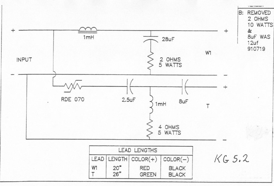
Well, work slowed down so I had a few minutes to play with the speakers. I swapped in those KG 5.2 crossovers in place of the originals. The basic difference is in the HP leg of the xover. Instead of the wacky 2.5uf and 3uF caps with a large 12 ohm resistor between the 1mH and ground, there's 2.5uF and 8uF with only a 2 ohm resistor from the 1mH to ground.
That allowed me to pull out the old xover boards for parts transplantation.
The more conventional KG 5.2 sounds more, well... conventional. I had them side by side, listening to a mono recording. There was a sort of "hhhhhhhhhhhh" coloration to the KG 4.5 version. The KG 5.2 equipped speaker has a bit less attack in the mids. It's easier to live with, so I'm going with it.
There has been a lot of mention of the supposedly lousy quality parts used in Klipsch xovers. The parts in these xovers are hecho en Mexico, with all Mexican capacitors and resistors. They look the same as Bennic parts, FWIW. I'd figure they'd be perfectly OK, but what do I know...
I have Panasonic ECQ (metallized film) 8.2uF at 100V and 2.7uF at 250V to put in. Will these be close enough to the 8uF and 2.5uF in the original?
Also, the 1mH in the KG 4.5 xover's HP leg looks like a better quality air-core than the 1mH HP choke in the later KG 5.2 version, so I'm hoping that makes a difference.
We shall see if these parts upgrades make any difference.
Also, the cap to ground in the LP section in the KG 4.5 is 33uF (NP electrolytic) while it's 28uF in the KG 5.2 xover. Considering these are electrolytics, and so are no better than 10% tolerance (+/- 3uF), do you think this will make an audible difference? Or will the larger than specified caps in the HP section (letting more highs thru) go well with the 33uF in the LP section (cutting off the highs a hair lower)?
But I think I can say that those of you who were telling me that the 4.5 crossover was totally weird... You was right!
--
10% doesn't really make that much difference and is often ignored when making significant changes like this. That said, you can usually hear a 10% difference but it is small.
By the way components with a 10% tolerance are usually better than 10%, although electrolytics will change with usage over time.
By the way components with a 10% tolerance are usually better than 10%, although electrolytics will change with usage over time.
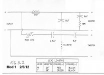
Here's the 5.2 crossover again:
I always notice with these shunt resistor crossover arrangements, that you can replace the inductor or capacitor plus 2-4 ohm resistor with a quarter of the reactive value and keep things similar.
Thus 28uF+2R becomes 7uf in the lowpass shunt arm here, and 1mh+4R becomes 0.25mH in the highpass shunt to give you roughly standard calculated crossover values and a more familiar look. And I'm getting about 3kHz crossover for the tweeter.
What makes this whole problem a nightmare is you really don't have any level to play with on the horn compression driver. Padding it with resistors will reduce efficiency, and adding Zobel will rolloff the deliberately lifted high end. You'll also be getting a lot of rubbish from the bass in the cone breakup region and above IMO.
You might pad it down though, and restore some high end with tone controls. John Linsley-Hood often suggested this where getting record player pickups right was problematic.
For clarity, the KG5.2-style crossover I have is actually labeled KG4.5. I think it might be a later version. It is identical to the KG5.2 schematic pictured above, but has 33uF in the LP section instead of 28uF.
KG4.5 used a K-1005-K 10" woofer. KG5.2 used a K-1001-K 10" woofer and a 12" passive radiator.
____________________________________________
Ah, I wish I knew how to figure out these things.
It turns out that my particular KG5.2-style crossovers have 33uF in the LP, not 28uF.
So 33uF+2ohms could be replaced by about 8.2uF? I'd be glad to do that.
I redid the KG4.5 crossover boards.
- In the HP part, I changed the 3uF cap to 8.2uF.
- In the LP part, I jumpered out the 12 ohm, let the 1mH go directly to ground.
The resulting sound was very close to the stock KG5.2-style crossover (that's labeled KG 4.5 for some inexplicable reason). There was a bit of a hole in the response that made female voices recede too far back, and a generally "washed out" midrange. So I put a 5.5 ohm resistor in the place where the 12 ohm used to be (where there's 4 ohms in the KG4.5 crossover, but I don't have any 4 ohm resistors). The sound from the modified KG4.5 crossover is now very close to the stock 5.2 crossover, except some of that "hotness" is back in the modded KG4.5 xover, but not bad when using the stock KG5.2-style xover.
I wonder if this is due to the fact that the 4.5 crossover has an air core 1mH in the HP, while the 5.2 crossover has a ferrite core 1mH? Higher DCR of the air core results in less attenuation? Less steep slope of rolloff?
Since I like the sound with the KG5.2-style xovers in, I tweaked them a little bit. Put a 220nF oil-paper cap parallel to the 33uF electrolytic, and bypassed the 8uF with a 100nF oil-paper cap. Bypassed the 2.5uF cap with a 30nF orange drop PS220 (mylar?). Those were just caps grabbed from my junk box. That only made a barely noticeable difference, maybe slightly better upper frequency clarity.
At any rate, I find the KG5.2-style crossover sounds much better to me than the original KG4.5 crossover. This is still a bright, in-your-face speaker, but it sounds a lot smoother this way.
I now have a pair of KG4.5 boards that can be played with. So, how about this (attached)?
--
PS - I have a box of chokes left over from my misspent youth. I have pairs of 0.17mH, 0.62mH, 1.2mH, and 1.8mH. Anything useful in there?
KG4.5 used a K-1005-K 10" woofer. KG5.2 used a K-1001-K 10" woofer and a 12" passive radiator.
____________________________________________
I always notice with these shunt resistor crossover arrangements, that you can replace the inductor or capacitor plus 2-4 ohm resistor with a quarter of the reactive value and keep things similar.
Thus 28uF+2R becomes 7uf in the lowpass shunt arm here, and 1mh+4R becomes 0.25mH in the highpass shunt to give you roughly standard calculated crossover values and a more familiar look. And I'm getting about 3kHz crossover for the tweeter.
Ah, I wish I knew how to figure out these things.
It turns out that my particular KG5.2-style crossovers have 33uF in the LP, not 28uF.
So 33uF+2ohms could be replaced by about 8.2uF? I'd be glad to do that.
I redid the KG4.5 crossover boards.
- In the HP part, I changed the 3uF cap to 8.2uF.
- In the LP part, I jumpered out the 12 ohm, let the 1mH go directly to ground.
The resulting sound was very close to the stock KG5.2-style crossover (that's labeled KG 4.5 for some inexplicable reason). There was a bit of a hole in the response that made female voices recede too far back, and a generally "washed out" midrange. So I put a 5.5 ohm resistor in the place where the 12 ohm used to be (where there's 4 ohms in the KG4.5 crossover, but I don't have any 4 ohm resistors). The sound from the modified KG4.5 crossover is now very close to the stock 5.2 crossover, except some of that "hotness" is back in the modded KG4.5 xover, but not bad when using the stock KG5.2-style xover.
I wonder if this is due to the fact that the 4.5 crossover has an air core 1mH in the HP, while the 5.2 crossover has a ferrite core 1mH? Higher DCR of the air core results in less attenuation? Less steep slope of rolloff?
Since I like the sound with the KG5.2-style xovers in, I tweaked them a little bit. Put a 220nF oil-paper cap parallel to the 33uF electrolytic, and bypassed the 8uF with a 100nF oil-paper cap. Bypassed the 2.5uF cap with a 30nF orange drop PS220 (mylar?). Those were just caps grabbed from my junk box. That only made a barely noticeable difference, maybe slightly better upper frequency clarity.
At any rate, I find the KG5.2-style crossover sounds much better to me than the original KG4.5 crossover. This is still a bright, in-your-face speaker, but it sounds a lot smoother this way.
I now have a pair of KG4.5 boards that can be played with. So, how about this (attached)?
--
PS - I have a box of chokes left over from my misspent youth. I have pairs of 0.17mH, 0.62mH, 1.2mH, and 1.8mH. Anything useful in there?
Attachments
Last edited:
- Status
- This old topic is closed. If you want to reopen this topic, contact a moderator using the "Report Post" button.
- Home
- Loudspeakers
- Multi-Way
- Taming harshness in horn tweeter