I would keep it all floating unless you have hum and noiseproblems,if so connect ground to main heatsink = earth. But not with a straight wire :
Power Supply for Power Amplifiers
Power Supply for Power Amplifiers
Attachments
Hi Igreen,
You may or may not need it depending are your set up. For me, It's the reason why my amp is dead quiet with the inputs floating, but I did have to lift earth ground from connecting to the chassis. Try it with and without to see what the difference is.
Regards,
Al
You may or may not need it depending are your set up. For me, It's the reason why my amp is dead quiet with the inputs floating, but I did have to lift earth ground from connecting to the chassis. Try it with and without to see what the difference is.
Regards,
Al
An issue
OK, channel 1 is working great, so I connect channel 2.
With the 100 ohm resistors across the fuseholders and the bias turned all the way down (no drop across the emitter resistors and v+ and v- measure correctly at the fuse terminals) I get a 1.1 volt drop across the + fuse and a 1.39 volt drop across the - fuse. The DC offset is -8.6v. PS Leds are illuminated correctly.
If I have the input shorted all 3 LEDs are lit and it looks good visually (except for the above measurements).
If I have the input open circ L5 does not illuminate; it does if I short the input and goes out when I unshort the input.
If I have the input open circ L5 does not illuminate; it does if I short the input and goes out when I unshort the input.
The voltage across the current limiting resistors are around +2.9V & -2.5V.
I suggest to check the orientation of LED L5 (Flat side is the cathode) and check the voltage across the zeners. Whilst the board is compact, it also make trouble-shooting more difficult and I blew one zener (ZD2) whilst checking its voltage.
Good luck with your trouble-shooting.
- Stanley
Here is something very odd.
The input terminal ground measures 9.8 ohms to the output terminal ground and to the PS ground.
The PS ground measures short circuit to the output terminal ground.
I think the amp is designed that way, the R39 lift the signal ground 10 ohms above the PS ground.
- Stanley
The DC offset of my 2 channels amp were fluctuating from -4.0 to -5.0 mv. All transistors were matched and I applied 35mv bias on the output transistors. I have a 8.5" x 4.5" heatsink and tempearture goes up to 50 degrees max. Is that bad or good?
On my F5 amp, I have a dc offset of -2.0 to -3.0 mv, which had been working great for a year and a half now. I would assume this would be okay also. Any thoughts?
Fred
On my F5 amp, I have a dc offset of -2.0 to -3.0 mv, which had been working great for a year and a half now. I would assume this would be okay also. Any thoughts?
Fred
Hi Igreen,
Did you resolve the issue with the amp that's not working?
Some thoughts. Is the heatsink connected to the amps ground? I think the short between the output and ground may be happening because the heatsink is grounded to the amp's ground, at least one of the thermal pads are not isolating the OT's collector from the heatsink, and the OTs are blown creating a short between the OT's emitter and collector.
If you haven't already make sure like Andrew pointed out that all the component orientations are correct.
Regards,
Al
Repairs?
The PS ground terminal measures short to the output ground terminal. Supposed to be like this right?
I have not had a chance to look at it yet except to remove the board from the heatsink- I'll try it in free air and first probe the output transistors to look for shorts. Perhaps two shorted to the HS? I did not actually connect board to HS and the HS was sitting on a wooden bench so not exposed to either ground or any voltage unless something was mounted badly.
In the meantime, would you mind letting me/us know a few critical junctions to probe and what voltages they should be (hopefully they are accessible on the board) -- and I am wondering whether testing should be done a full rails or to be safe a smaller voltage (easy as I'm using a VARIAC).
EDIT- here is a link to a very large pic of the board. The q's look to be in the correct orientation except for Q1 and Q2 where were supposed to be backwards. This was before the fuseholders and 100 ohm resistors were installed and note that an external bridge is being used.
LINK
? There is no short from output to ground ?Hi Igreen,
Did you resolve the issue with the amp that's not working?
Some thoughts. Is the heatsink connected to the amps ground? I think the short between the output and ground may be happening because the heatsink is grounded to the amp's ground, at least one of the thermal pads are not isolating the OT's collector from the heatsink, and the OTs are blown creating a short between the OT's emitter and collector.
If you haven't already make sure like Andrew pointed out that all the component orientations are correct.
Regards,
Al
The PS ground terminal measures short to the output ground terminal. Supposed to be like this right?
I have not had a chance to look at it yet except to remove the board from the heatsink- I'll try it in free air and first probe the output transistors to look for shorts. Perhaps two shorted to the HS? I did not actually connect board to HS and the HS was sitting on a wooden bench so not exposed to either ground or any voltage unless something was mounted badly.
In the meantime, would you mind letting me/us know a few critical junctions to probe and what voltages they should be (hopefully they are accessible on the board) -- and I am wondering whether testing should be done a full rails or to be safe a smaller voltage (easy as I'm using a VARIAC).
EDIT- here is a link to a very large pic of the board. The q's look to be in the correct orientation except for Q1 and Q2 where were supposed to be backwards. This was before the fuseholders and 100 ohm resistors were installed and note that an external bridge is being used.
LINK
Last edited:
Hi Fred,
The numbers your reporting look good. Have you had chance to play music and evaluate the amps performance?
Regards,
Al
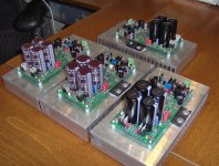
Thanks Al for your response. I did try played some music and its sonic performance is pretty good. I haven't tried for longer listening since I'm still working on three more boards. I'm done with 4 channels and three more to go for a home theater 7 channel amp. The four channels would be just the 60watt version.
Hi Igreen,
Just a suggestion, you might wanna checked the J1, jumper wire, soldered on the back of the board. That is to close to the base pad of Q8 and can easily get shorted. If you put an ohmeter between J1 and base of Q8, that should measure 22 Kohms if I'm not mistaken.
Hi Fred,
That's great to hear that you have four amps working.
Thanks for pointed out that J1 is dangerously close to Q8's base. If I order more boards I'll make sure to put some more space between the two pads.
Igreen, along with Fred's suggestion also carefully check all your solder connections.
Al
That's great to hear that you have four amps working.
Thanks for pointed out that J1 is dangerously close to Q8's base. If I order more boards I'll make sure to put some more space between the two pads.
Igreen, along with Fred's suggestion also carefully check all your solder connections.
Al
Fred,
I'd like to hear more about the amps performance when your done if you don't mind.
One of the nice things about this design is that you can configure the PCB in several different ways. I found that when using all the small signal transistors you get a very low THD resulting in a very detailed precise sound, but by removing cascode Q9 and Q12 in the 60 watt version the sound becomes softer sweeter more tube like. Probably because 2HD increases by about 10db.
Anyway, something to think about.
Al
Last edited:
https://www.fairradio.com/
#401-21 Go to "Products" page, select "Transformers", select "Low Voltage Transformers", scroll down.
I just ordered a 70 vct transformer rated @ 350 VA and including several taps that may be of value. Weight: 16 pounds.
The cost: $12.95 + Shipping
It is not shielded, we'll have to deal with that.
#401-21 Go to "Products" page, select "Transformers", select "Low Voltage Transformers", scroll down.
I just ordered a 70 vct transformer rated @ 350 VA and including several taps that may be of value. Weight: 16 pounds.
The cost: $12.95 + Shipping
It is not shielded, we'll have to deal with that.
Last edited:
Fred,
I'd like to hear more about the amps performance when your done if you don't mind.
One of the nice things about this design is that you can configure the PCB in several different ways. I found that when using all the small signal transistors you get a very low THD resulting in a very detailed precise sound, but by removing cascode Q9 and Q12 in the 60 watt version the sound becomes softer sweeter more tube like. Probably because 2HD increases by about 10db.
Anyway, something to think about.
Al
No problem Al, I'll keep you posted. I still have a long way to go and one of my problem is the case for my amp.
I'll try experimenting as what you mentioned. One of my purpose in building a 7 channel amp is for biamping.
Attachments
- Status
- This old topic is closed. If you want to reopen this topic, contact a moderator using the "Report Post" button.
- Home
- Amplifiers
- Solid State
- SymAsym - "The Sequel", AAK's PCB Builders Thread