Hi Ed
Your enclosure is looking real sharp. Are you all set for the Midwest AudioFest show?
It's to bad that I live so far away from Springboro Ohio, it would of been awesome to see your setup and everybody elses, and to demo my new speakers that was partially inspired by Parts Express’s Tubular Speaker Project.
Regards,
Al
...late to respond, no internet yet in my sister's new home in N.C., where the family had some good times together.
I am going to MwAF. I plan to have things ready, if work doesn't conspire against me.
I need to assemble the circuit to drive the meters that I referred to as VU...really they'll be power meters, but the bling will still be there. I'll ventilate the case with bottom holes and wire mesh or expanded metal on the top.
Hey guys,
I apologize for being away for so long, I've been busy working on other projects among other things. What's up with this thread, it's dead.
How about some updates?
Igreen did you get the amp that was giving you problems working?
How's it going Ed, you must be close to firing up the amps?
Al
Not working, would appreciate some debug advice.
As in - where to probe and what voltage it is, I've got a variac so can bring it up slowly. Yes I know that I can measure the working channel but to prevent shooting in the dark what are the key voltage points to measure and what should they be?
issue-
Since I am mounting one board opposite of the other board I of course connected Q17 (bias) transistor correct on the working board and backwards on the nonworking board. On the nonworking board the Emitter and Base are swapped with where they should be.
I fixed this and I still get the same issue which is a lot of DC and L5 only illuminating if the input is shorted (does not light if input not shorted). Did I blow anything nearby Q17 with my initial short full voltage test, if so which components are recommended to be replaced?
I looked at the hires photos today and compared both boards, everthing appears to be installed correctly. EDIT- and Q17 does not measure short circuit between any terminals so appears to still be ok?
Hi Igreen,
To start check all the DC PS voltages including the voltage at the base of Q13 and Q16. You should get about 15 volts indicating that ZD1/ZD2 are Ok. After that check the currents listed below against your amp to see how they compare. List the values and will go from there.
R10,R11 -> 21ma
R23,R24 -> 1.7ma
R31 -> 1.0ma
R21 -> 3.6ma
R22 -> 2.5ma
R19 -> 4.5ma
R33 -> 8.5ma
R32 -> 2.3ma
R16 -> 8.5ma
R37,R38 -> 2.5ma
Since L5 lights up with the input shorted it's possible that Q1/Q2 could be damaged. You might want to replace them to see what happens. Make sure R39 measures 10ohms.
Al
Hi Igreen,
To start check all the DC PS voltages including the voltage at the base of Q13 and Q16. You should get about 15 volts indicating that ZD1/ZD2 are Ok. After that check the currents listed below against your amp to see how they compare. List the values and will go from there.
R10,R11 -> 21ma
R23,R24 -> 1.7ma
R31 -> 1.0ma
R21 -> 3.6ma
R22 -> 2.5ma
R19 -> 4.5ma
R33 -> 8.5ma
R32 -> 2.3ma
R16 -> 8.5ma
R37,R38 -> 2.5ma
Since L5 lights up with the input shorted it's possible that Q1/Q2 could be damaged. You might want to replace them to see what happens. Make sure R39 measures 10ohms.
Al
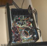
Thank you Al. Due to these nifty tips I found the error, a pin on Q14 with a flaky solder joint. Now channel 2 is up and running with channel1, In fact its together and playing music in my old Pass F5 case using the Pass power supply. I've added a softstart and fan/ temp sense circ.
I have 4-5 mV on Ch1 and 45 mV on channel 2 of DC offset. No audible hum or hiss. Heatsink not grounded...may do that later.
See attached pic.
Attachments
Last edited:
Hi Symasym builders, hi Al,
tried to power up my symasym today. Did it after the how to, so I soldered 100R resistors instead of fuses. Unfortunately there was smoke
You wrote, one should turn poti counterclockwise to the end. So I did. I measured and found out, the poti is showing 0R in this endposition. Probably this is wrong, isn't it?
Regards, Ernst
Hi,
I am refering to these caps
C1,C2,C9,C11,C12,C13 Poly/Film 0.1uF 63V 505-MKS20.15/63/5
The BOM indicates 0,1uF while the mouser réf. is a 0,15uF .... kinda confusing.
TIA,
Max
EDIT: Same goes for the C1, 0,1uf in the BOM, 0,15uF in the Mouser ref. C10 Poly/Film 0.1uF 63V 505-MKP20.15/100/5
I am refering to these caps
C1,C2,C9,C11,C12,C13 Poly/Film 0.1uF 63V 505-MKS20.15/63/5
The BOM indicates 0,1uF while the mouser réf. is a 0,15uF .... kinda confusing.
TIA,
Max
EDIT: Same goes for the C1, 0,1uf in the BOM, 0,15uF in the Mouser ref. C10 Poly/Film 0.1uF 63V 505-MKP20.15/100/5
Last edited:
Done!
My SymAsym is singing since a couple of days and it sings very very well (I didn't know my speakers were so good!).
I tried to build it carefully and all went without sparkles, smoke, hum, plop, sshhh...
Offset : 1,5 and 2 mV
2 transfos 2x30V ; 250 VA (yes , it's not 2x35V, but I had them...)
Now the case ...
Many thanks, Al. Congratulations, Michael Bittner!
Cordialement
J
Hello everyone. I have been on a mission to finally finish building my symAsym for the last month. I assembled the first board and upon the testing procedure I have 2 smoking 100ohm resistors (inplace of fuses). I am using a 34v trafo and rail voltage is 48v. L3 is lit brightly and L4, L5 and L6 are dim. Aak has been helping me and he suggested that I build the second board. I did that over the weekend and the same thing is happening again, smoke and L3 brightly lit and L4, L5 and L6 are dim. So this leads me to believe the value of some component I am using must be incorrect. I measured all the resistors and they are correct. I will test the mica caps tonight anyone else has any suggestions?
Here are some pics of the second board (sorry it looks like a mess. I have been unsoldering and unsoldering almost everything. Im surprised the pcb hasnt disintegrated yet.)
Uploaded with ImageShack.us
Uploaded with ImageShack.us
This is the case I built for my symAsym, I hope I can get this project completed soon
Uploaded with ImageShack.us
Here are some pics of the second board (sorry it looks like a mess. I have been unsoldering and unsoldering almost everything. Im surprised the pcb hasnt disintegrated yet.)
An externally hosted image should be here but it was not working when we last tested it.
Uploaded with ImageShack.us
An externally hosted image should be here but it was not working when we last tested it.
Uploaded with ImageShack.us
This is the case I built for my symAsym, I hope I can get this project completed soon
An externally hosted image should be here but it was not working when we last tested it.
Uploaded with ImageShack.us
I bought 6 of the version 1.3 amp boards quite some time ago. I have now returned to the project having completed all the boards(except for output transistors on 4) I have tested the 8 boards which are complete (complete with dim bulb tester).
The bad news is 3 failed the smoke test. The somewhat better news is that the other 5 all passed the smoke test (all 8 board display the correct rail voltages of +/- 52.3 V which is inline with noload conditions for a 35-0-35 transformer I'm using). Testing the 5 boards with the 100R safety resister inplace I measured voltage drops accross this resistor ranging from 1.4V tp 1.7V. The assembly manual for version 1.4 indicates this drop should be 2.5-3.5V. Should the voltage drop for version 1.3 be the same or, if not, what should it be (and do I have an issue with the 5 smoke free boards)?
Thanks,
SteveA
Coincidently I've just returned to this project too. I built 2 boards, both failed the 100 ohm test . Returning to the boards and reading the thread I see that Q20 and Q21 were recorded wrongly in an early BOM, which I missed - D'oh.
So I've put that right. Now at least the 100 ohm resistors don't smoke. However, I'm only getting 2V and 1.5V across them.
Does anyone have an idea?
Is there anyone out there?
So I've put that right. Now at least the 100 ohm resistors don't smoke. However, I'm only getting 2V and 1.5V across them.
Does anyone have an idea?
Is there anyone out there?
Hi SteveA, chalkandtalk,
Let me know what happens on the boards that are measuring less than 2.0V across the safety resistors if you turn pot R36 clockwise. Make sure to do it slowly. It may take several turns before you see any change. Does the voltage across the 100 ohm resistors stay the same or does it increase? If it increases make sure to keep it below 3.5V so that resistors don't over heat.
Lets continue this discussion on the Rev_1.4 builders thread here.
http://www.diyaudio.com/forums/soli...-sequel-aaks-rev_1-4-pcb-builders-thread.html
Thanks!
Al
Last edited:
- Status
- This old topic is closed. If you want to reopen this topic, contact a moderator using the "Report Post" button.
- Home
- Amplifiers
- Solid State
- SymAsym - "The Sequel", AAK's PCB Builders Thread