2nd channel well underway
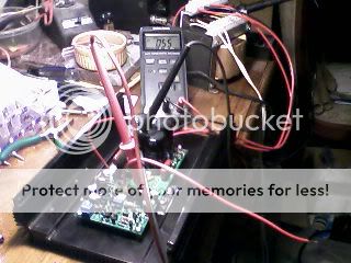
resistors in place, 2.76 & 2.54V across them... 3 mV offset
I'm going for the 55 mV called out in the Testing section of the Assembly Instructions. I believe at this point the sinks I'm using are big enough...~9" high...I just have them laying on the bench so they won't fall any further...they do warm up faster that way.
Fuses in place. Second channel is 5-6 mV offset.
Yee Haw!
I'll be working on the back panel over the next few days, get closer to the finished assembly, repeat the bias set-up, so looking forward to a listen. The front panel will take a while longer...it needs some thought...I have VU meters from a scrapped cassette deck I hope to use there.
Al, You're Alright!
I finally finished my boards last night, and couldn't resist powering them up.
First I checked the voltages at the fuse ends: +/- 55V so OK there.
However, I then put the 100ohm resistors in place of the fuses, and they blew!
Al: Somewhere your instructions say to install the variable resitor with the screw a certain way round. I read this after I had installed mine, unfortunately - so mine are the wrong way round. I thought that this would not make any difference, however and continued. But would it be better to remove them and turn them round?
cheers
Aidan
AndrewT from lovely Scotland did most of the thinking and most of the math in post #133. I just follow along and measure, if I can. Preserves my gray matter.
Grufti,
I'm interested in more of your experience wrt setting the bias. How is "optimum" determined?
PS, I never mentioned my outputs are NOS Toshiba 2SA1302/SC3281
this damage would not have happened if you had used the mains bulb tester as so often advised for all new mains powered projects and for every time you modify a project.I then put the 100ohm resistors in place of the fuses, and they blew!
One thing I noticed about the relationship between the channels was the temperature of the sinks.
I had one channel which ran considerably warmer that the other. I was able to keep my hand on the sink continually without the impulse to remove it. I let the music continue.
At about ~40 minutes into operation the temperature seemed to equalize. The temp of the hotter channel settled to ~equal the other.
Now, somewhere about that time the soundstage seemed to "open up". I won't place much emphasis on this. FM radio was the source. The music selection at that time may have changed to one with more "ambience" in the recording.
All the same, switching to cd's...I'm hearing things now I was not previously...music...and no one else is home...
I have started to look over my boards and check I have the right components in the right place. So far I have checked the transistors which are all fine.
As I said earlier I have the variable resistor placed the wrong way round. Will this make any difference?
Secondly: when I put the fuses in and power up I read 55V between speaker output and ground. Does this indicate blown 5200/1943s?
Your help would be very much appreciated
Aidan
As I said earlier I have the variable resistor placed the wrong way round. Will this make any difference?
Secondly: when I put the fuses in and power up I read 55V between speaker output and ground. Does this indicate blown 5200/1943s?
Your help would be very much appreciated
Aidan
Hi Aidan,
If you placed the multiturn resistor the wrong way around it will also work the other way around. To increase the bias current turn the multiturn anti-clockwise, to decrease the idling current turn it clockwise. I would personally sugest to desolder the multiturn.
Your outputs semiconductors are most probably blown because off the intial high bias current used. As Andrew suggested use a light bulb and/or the resistors as suggested by AAK.
regards,
Piersma
Secondly: when I put the fuses in and power up I read 55V between speaker output and ground. Does this indicate blown 5200/1943s?
Your help would be very much appreciated
Aidan
Aidan,
Did it blow the fuse when you get 55V at the output of the amp? Check with an ohmmeter if the resistance between collector and emitter of the 5200 is 0 ohms. I assume you might have a bad transistor or maybe a short circuit on that section of the output stage.
Thanks Piersma and Fredlock for advice.
I have now turned the variable resistor around. I have also installed new output devices. Fingers crossed.......
Fredlock: Previously one fuse would blow when powered. Anyway after installing new output devices I measure infinite resistance between speaker out and ground with no power connected.
I have now turned the variable resistor around. I have also installed new output devices. Fingers crossed.......
Fredlock: Previously one fuse would blow when powered. Anyway after installing new output devices I measure infinite resistance between speaker out and ground with no power connected.
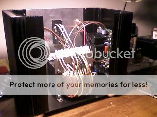
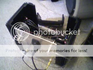
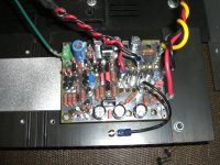
This shows the amp coming together. This open side is intended to be filled with VU meters and panel. The transformer has more taps than I expect to use...I didn't want to throw away the option for 18, 20, 25 VCT, 6 or 24 vac. That is the reason I installed the terminals above the tranny.
Just one thing before I power up - If I use 100ohm resistors instead of fuses what power rating should they be?
The light bulb tester sounds great but will take me a while to build one.
1/2 watt will be okay. Just follow the Assembly instruction of Al and you should be fine.
It is just 4 components.The light bulb tester ... will take me a while to build one.
An input plug top, an output socket, a bulb holder and a box to protect you.
Hi All,
Here's an update on my latest projects.
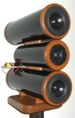
I've been working on a new speaker design using PVC pipe for a while now and I finally completed it this weekend. It looks really nice and sounds incredible. I'm still waiting for some crossover parts to tidy things up. I've been currently testing it with passive filters seen in the pic but I’d also like to test it with active filters. If I decide to go with the passive filters instead of actives they'll go inside the tweeter compartment.
In order to test my speaker design using active filters I decided to remove the PS from my DTV Rev_1.3 amplifier so that I can fit four amplifiers on the heatsinks and enclosure that I'm using. While making the modes I added a new bias circuit (similar to Roender's latest design) to the input differential that drops the part count from 18 components to 11 without affecting the sound quality. I also moved the OT's so they now mount underneath the board allowing for 3" heatsink instead of 4". The board measures 2.87" x 3.5".
For the active filter test I'll run the amps using +/-36V rails. For the mid/bass drivers I'll bypass cascode Q3&Q4 while using all four output transistors. For the tweeter I'll bypass Q3&Q4 and most likely Q9&Q10 to increase the even order harmonics for a sweeter warmer sound, and use a single pair for the outputs.
I've attached the new amplifier schematic, a pic of the built and tested amplifier prototype, and a pic of my new speaker.
Regards,
Al
Here's an update on my latest projects.
I've been working on a new speaker design using PVC pipe for a while now and I finally completed it this weekend. It looks really nice and sounds incredible. I'm still waiting for some crossover parts to tidy things up. I've been currently testing it with passive filters seen in the pic but I’d also like to test it with active filters. If I decide to go with the passive filters instead of actives they'll go inside the tweeter compartment.
In order to test my speaker design using active filters I decided to remove the PS from my DTV Rev_1.3 amplifier so that I can fit four amplifiers on the heatsinks and enclosure that I'm using. While making the modes I added a new bias circuit (similar to Roender's latest design) to the input differential that drops the part count from 18 components to 11 without affecting the sound quality. I also moved the OT's so they now mount underneath the board allowing for 3" heatsink instead of 4". The board measures 2.87" x 3.5".
For the active filter test I'll run the amps using +/-36V rails. For the mid/bass drivers I'll bypass cascode Q3&Q4 while using all four output transistors. For the tweeter I'll bypass Q3&Q4 and most likely Q9&Q10 to increase the even order harmonics for a sweeter warmer sound, and use a single pair for the outputs.
I've attached the new amplifier schematic, a pic of the built and tested amplifier prototype, and a pic of my new speaker.
Regards,
Al
Attachments
- Status
- This old topic is closed. If you want to reopen this topic, contact a moderator using the "Report Post" button.
- Home
- Amplifiers
- Solid State
- SymAsym - "The Sequel", AAK's PCB Builders Thread