ostripper said:I tried to recreate otala's work and failed , some one else did this..
(attached) that otala VAS dissipates 20ma (large heatsink) and uses old devices..
OS
In the amp Matti Otalla, he has the old Phillips BD139/140 (190Mhz), are no longer manufactured and is not easily substitute.
I talked to use the compensation Miller, short circuit VAS
Can attach your amplifier in file .asc...
Can attach your amplifier in file .asc...
Edit out the .TXT
You must get winrar or winzip..
OS
Attachments
No, I would like the file is supersym (.asc.zip)

As simulate file .TXT
I have winrarYou must get winrar or winzip..
As simulate file .TXT
You lucked out , I just did the cascoded Jfet version , I will also include the original (the one I'm listening to now).
Anyone please comment , I did notice the jfet's doubled the THD20
to .014% max (up from .007%) I used 2N4393 , mouser still has them at $1.84 apiece !! these devices do not have the gain of the KSC's so less degeneration was in order. (22r instead of 100r).
In the .zip is the original and the new cascoded version , make sure
all 3 files are in the same folder.
OS
Attachments
ostripper said:
Anyone please comment , I did notice the jfet's doubled the THD20
to .014% max (up from .007%) I used 2N4393 , mouser still has them at $1.84 apiece !!
See the open loop in 20Khz, should be reduced
See the open loop in 20Khz, should be reduced
Explain further , or .. better yet, modify the .asc file and post it with the changes.
OS
Hi ostripper,
Everything looks like you are on the right track, even if someone wants to use mosfets.
2SK170 are still floating around out there, you can also use a surface mount dual jfet pair, or just two singles. These could be mounted on an adapter PCB to make life easier.
Have a look at J201 ~ J203 and J210 ~ J212. LS846 might be good. I have a short list of current devices around here somewhere. There are more devices available as surface mount parts, but that might actually work to our advantage. It's a good excuse to mount these parts in the diff pair for better heat sharing and freedom from air currents across the leads. Additional shielding can also be applied.
The reduction in gm may not be a huge problem at all. In fact, you may end up with lower order effects, and the current could be increased some to raise the gm. Remember, no base bias currents to worry about with Jfets. That may also mean that the feedback network can have a higher impedance. Remember that the 2SK170 still has lower noise than many BJTs do...
So, it looks like you have options still.
-Chris
Rafael.luc said:
Could please post the models: KSC1845, KSC2690, KSC3503 and KSA1381.
Ignore my message, had not seen the file txt in folder...
That color is Led?
by raphael -Could please post the models: KSC1845, KSC2690, KSC3503 and KSA1381.
They are in the supersym.txt , the supersym.asc will automatically
include those models when you run the sim. OR , you could copy/paste to your standard.BJT file in LT.
4mA in Vas! needs to triple output or Mosfets as driver.
That is what I originally thought , simulation at a 2R load and real life use with 3R loads have shown almost no loading of the VAS.
But feel free to run this VAS at 7-10mA (47R - R16), it is not the symasym one.
Very good, TDH at maximum power ?
.007% at 60v p-p 20khz
@ at a nuclear 120v p-p... .012% (3v input)
Red ..1.6 - 1.8V VfThat color is Led?
by anatech - So, it looks like you have options still.
And so shall the constructor , on the one PCB , it shall be easy.. in a neat and professional way , to go 1. plain jane BJT , 2. cascoded BJT , or 3. cascoded JFET . All with documented support (jumpers and component changes).
OS
4mA in Vas! needs to triple output or Mosfets as driver.
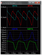
Just to show an unrealistic output and load, (2R and 120v p-p)and how this loads the VAS at 4ma, the (attached) file shows (top plot)
current through driver basestoppers and (bottom plot) total Ic of the Mje15032/33 , not even close to their SOA , even at 100 C.
I would not want to be the speaker or touch the wire at this level..
OS
Attachments
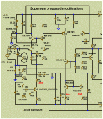
I think I see a mistake in your latest schematic. In order to have cascodes for J1 and J2 the resistor R13 needs to switch places with diodes D4, D5 and capacitor C7. In this case, the cascode voltage must be referenced to GND not to power supply line.
Hi, bluesky . You mean use a 15V zener referenced and decoupled from ground ? That does seem to simplify and improve things. It also is confirmed by the Ampslab zener arrangement. Thanks
OS
By piersma - I have this thing up and running for some time now, take a look at the cascode arrangement.......
I see where THAT began
Cdom question
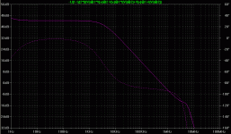
Was simulating the loop gain with middlebrook probe and found the amp stable without C7, C8. The gain plot didnt move up in freq. very much at all. Am I doing something wrong, is this amp that stable? And if it is why not use lower cdoms? Heres the plot.
Was simulating the loop gain with middlebrook probe and found the amp stable without C7, C8. The gain plot didnt move up in freq. very much at all. Am I doing something wrong, is this amp that stable? And if it is why not use lower cdoms? Heres the plot.
Attachments
the input cascode can be referenced to signal ground or to input pair emitter/source tails.blueskynis said:the cascode voltage must be referenced to GND not to power supply line.
I don't know which, if any, is better.
Re: Cascode arrangement
 .
.
After countless versions of SymAsym in lots of setups, it is still among the best amplifiers I have ever heard.
This one seems to be a good chance to scale things up a little (my original ones are a little bit weak to drive the current 103 dB/2,83V/1m bass units).
Piersma, mind telling something more? Rail voltages? How's sonic performance?
I am very much interested in this SymAsym version. Even if Roender doesn't like the roots of this design any more, me doesPiersma said:hi all,
I have this thing up and running for some time now, take a look at the cascode arrangement.......
After countless versions of SymAsym in lots of setups, it is still among the best amplifiers I have ever heard.
This one seems to be a good chance to scale things up a little (my original ones are a little bit weak to drive the current 103 dB/2,83V/1m bass units).
Piersma, mind telling something more? Rail voltages? How's sonic performance?
- Status
- This old topic is closed. If you want to reopen this topic, contact a moderator using the "Report Post" button.
- Home
- Amplifiers
- Solid State
- Symasym - the next generation (supersym)


