Why mosfets, I have MJL21193/93 
Looks good
Though I still dont understand those big solderpads
Are component holes really that big
About component leads holes
I have been thinking whether it might be much better to place the holes at the side of copper line, and not in the middle
Looks good
Though I still dont understand those big solderpads
Are component holes really that big
About component leads holes
I have been thinking whether it might be much better to place the holes at the side of copper line, and not in the middle
Hi tinitus,
It would have been nice to set up a voltage amplifier PCB and two kinds of output PCB. That way you could build it either way. This makes me wonder if the existing PCB couldn't be used by changing a few component values.
-Chris
Same here.Why mosfets, I have MJL21193/93
It would have been nice to set up a voltage amplifier PCB and two kinds of output PCB. That way you could build it either way. This makes me wonder if the existing PCB couldn't be used by changing a few component values.
-Chris
It would have been nice to set up a voltage amplifier PCB and two kinds of output PCB.
You guys move faster than me... wow!! I had to fix 2 leaky roofs on the smoky mountain "chalet" today (no wet amps) so I have been slow.
What I have done is build a single pair IRFP version. All that would be needed is extra pads for the gate protection and the pads for a type 1 EF (2 Re's to OP) in the driver section. IF one wanted to use the MJL/NJW BJT's , just omit the gate diodes , jump the 2 type 1 Re's with a single resistor (self type 2 EF) ... BJT or FET , your choice.
I am working on an improved CCS (courtesy of waveborn) and plan to do the full cascoded LTP with this MOSFET version. Ampslab has a very similar kit to this supersym2 (the HX200) . They (he.. M chua) , drives the HX IRFP's directly off the VAS
.. I don't like the idea of driving all that gate capacitance from my low current version , so some fast drivers might be the best. (ampslab runs the HX VAS at 10mA +).Why mosfets, I have MJL21193/93
It could be done ,but the 21193/4 have a much lower Hfe than the njw's .. so a triple EF or higher gain drivers (2sa1837 - 2sc4793) would be required. Even as the 21193 is the heafyest BJT around , it still has barely half the SOA at 80v than the IRFP240 (2 pair IRF's = 4 pair MJL's
)... plus , driving 4 pair of IRFP's requires only < 1ma from the driver pair versus 100's of ma for a BJT OP stage.OS


Hi ostripper,
Yes, I figured we could use the O/P board for both versions.
I wonder if a FET would work as the VAS buffer. That should reduce the dependence on output devices and gain. This technique has been used in the Revox B242 - sort of. Mosfets are used as the actual driver transistor instead of right off the VAS.
Hints for the newer CCS you are trying out? I am currently working on something where the CCS is being examined. Anatoliy?
Thanks, Chris
By homemodder - Anatech, try triple consisting of bjt drivers but mosfets as final outputs, gives very good performance and gets rid of the mosfets lack of deep down thump bass and involvement in low mid frequencies.
That is an interesting assessment , homemodder. Have you used the IRF's in this way?? I have been reading various info on MOSFET OP stages , and except for being biased "hard" into class A , many people (rod elliot - ESP) believe the non- linear characteristics of fet's in the crossover region make them undesirable as class B OP,s.
In the other camp , Quasi uses them in his NMOS amps , Ampslab and many others sell "hi -fi" kits using them. Using just 1 pair (IRFP240/9240), my scope tells me that at a much higher bias (120mA) , crossover distortion mimics a BJT pair at 60-70ma. Since I am making a separate driver board and have 77v available , I will try a triple. If you could , homemodder , could you just post a "clip" of this BJT-BJT-MOSFET triple OP stage (you can keep the rest a secret).
OS
Os I use them this way in several amps now, depends on the use, for subs I still prefer bjt outputs. I use the japanese equivalents. With this output and a frontend that is practically a copy of your design exept for cascoded fet input I get measured by a lab 0.009 thd at 120w output. With 3 pairs of 2sj200 youll easily get 150 watts 8ohm which is what I designed for, 4 ohm loads upto 240w load if you use good heatseaking, this is conservative but I have to think of extreme temp in car use. I dont see a problem using IRFPs for much higher power but I havent tried it for that. I find it more stable than bjt triple output and one gets good thd performance. As is I use in car amp to power mid and tweeters where I like the sound of these fets but it works just fine full range.
I have no problem showing, I know at least 2 highend companies using triples like this in their designs.
I have no problem showing, I know at least 2 highend companies using triples like this in their designs.
Attachments
By homemodder - I have no problem showing
Thanx , I now know I am not too far off.
By carefully comparing the 2sj200 vs. the irfp9240 , the only differences are the irf's killer SOA @ 80v and the 2sj has lower input capacitance. I might do something unique , use 2sa1381/sc3503 (predriver) , njw0281/0302.. HA as the main drivers (bias them "hot".. 100+ma - big 33r/2w Re) , to drive my 3 pairs of IRF's.Now to the "why".
why does it sound better as a triple? , does "swinging" 10k Pf gate capacitance with the added buffering of a triple EF really have an impact on the bass as you say. In other words .. technically , what is happening ?OS
Os I cannot explain technically why this is so, Im not sure what the answer is. Because audio is subjective, others may think the amp gets bass heavy, also depends on music taste, people that like jazz and classical like the sound results with normal driving of mosfets but Im a rocker and my clients want their number plates shaking off the car once in a while so I searched for a way with mosfets. Its obviously the way mosfets get driven although doing triples might seem to much for mosfets as it doesnt take much to drive them.
I ve used other ways too with even better results, totem pole drive. Works like a charm but more complex. Anyway for those that figures are important the triple setup does show better THD specs.
I ve used other ways too with even better results, totem pole drive. Works like a charm but more complex. Anyway for those that figures are important the triple setup does show better THD specs.
hi all,
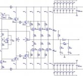
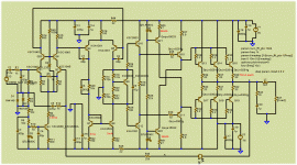
I have this thing up and running for some time now, take a look at the cascode arrangement.......
Someone has requested earlier as well, but could you please tell us about the supply voltages and sonic qualities of your cascode amplifier. Thanks.
I see some have built these ... my amp has gotten a little lonely , but has been rock solid for 3 months now.
My latest upgrades have been implemented successfully with absolute stability. The most obvious thing that has changed is the bass "slam" with the "T3T" triple (attachment 1 ) .
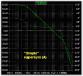
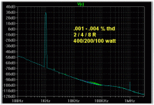
The other factors with the "new" version is the ultralow THD , which now is both load and frequency invariant . The cascode (I just added it) allows the use of SMD matched input pairs and lowers the initial offset to just .1-.2mV. FFT wise , I think one can not get much better (simplicity vs. low H3/5/7 - almost disappears). the OLG plot is very tame with no ringing or oscillation , even into difficult loads (10uf - capacitive).
I have yet to do the full upgrade with separate OPS / input boards and 5 pair of
the killer NJW21193/4's , but this will happen soon.
OS
my amp has gotten a little lonely , but has been rock solid for 3 months now. My latest upgrades have been implemented successfully with absolute stability. The most obvious thing that has changed is the bass "slam" with the "T3T" triple (attachment 1 ) .
The other factors with the "new" version is the ultralow THD , which now is both load and frequency invariant .
The cascode (I just added it) allows the use of SMD matched input pairs and lowers the initial offset to just .1-.2mV. FFT wise , I think one can not get much better (simplicity vs. low H3/5/7 - almost disappears). the OLG plot is very tame with no ringing or oscillation , even into difficult loads (10uf - capacitive).I have yet to do the full upgrade with separate OPS / input boards and 5 pair of
the killer NJW21193/4's , but this will happen soon.
OS
Attachments
OS, would you speculate that your Mosfet triple version would be better than the BJT one?
Have you tried lowering Cdom from 68pf and connecting a 47pf between the 2 VAS collectors, as Rafael has done?
I see the input cascode but SMD parts have not been specified.
I personally favour Mosfet outputs, having done many Lateral and Vertical types. Of the latter, examples are Bengt Olson's N-channel, Anthony Holton's N-channel, Quasi's N-channel and Stochino's Fast Amplifier. All of them are great performers of varying degrees and to a large extent better than any BJT amps I have tried.
Hi SamuelRafael.luc, have you built the amp in post #172? If yes, tell us how it sounds. Thanks.
It not was constructed and also do not have the PCB..but I will build a version lower power (50W-8R).
- Status
- This old topic is closed. If you want to reopen this topic, contact a moderator using the "Report Post" button.
- Home
- Amplifiers
- Solid State
- Symasym - the next generation (supersym)