sdman said:Joe, Have you breadboarded post #64 and what would be a good jfet for the front end?
Not yet, although it does simulate well. The FETs I would look for are 2SK1104 (single) or LS840 (dual). I don't know about real-world availability of these devices, but if it's a problem, you could use a nice small-signal MOSFET such as the ZVN3310 in matched pairs. With these in the front end, you could double the front end supply voltage for an 800W (8 ohm) amp, assuming your output section can take it.
"I made some simulations "
Maybe I should buy a simulator, and should not have used my Sound Technology 1700, Crown IMA, and not looked at the distortion output on my 'scope?
Perhaps I can't hear, or the big B&Ws, KEF, and Magnepans did not have sufficient resolving power?
Perhaps I was fooling myself to replace the LF353 with a higher current opamp, the ceramic coupling caps with film types, and adding power supply bypass caps(after all, none of those changes made a measureable difference in frequency response)?
It's an interesting concept, and I have a 40-40-40-40 2KVA transformer waiting for me to build a 150W/8R version using all FETs(when I can figure out the bias).
Joe Berry: Try only one diff pair to drive both sets of outputs. It can be done!
Hi all
I can not say about the 9. The 9+ deliver 65 W (8 Ohm ) as nominal power.
One can easily measure 80 Wrms (8 Ohm) and 160 Wrms (4 Ohm) before clipping, that is
voltage difference with a peak to peak value of about 72 Volts.
The liming factor is in the Opamp dual supply of about +-21/22 Volts (then will come
the 45 V floating supply). Drop this value
and the power will drop too and viceversa.
The Sumo 9+ THD curve has a near constant value on both 8 Ohm and 4 Ohm.
For load value below these I'll say later (see attached graph from simulatio).
Speaking about simulations, are you sure to utilize the correct schematics?
I advice you to refer here
http://www.geocities.com/fscarpa58/schematics/nine_plus.pdf
May be you have exchanged 8 and 4 Ohm and these appear data coming from an incorrectly biased 9 and not from a proper set up 9+.
I own two 9+ and they perform identical. I mean
electrically, meausered at my lab.
If correctly set up and if no fake devices, the npn pair remains OFF at both 8 and 4 Ohm irrespective of the power.
They switch ON only with smaller loads (3 Ohm at 120 W)
Bongiorno added that trick to 9+ to increase the ability of
the old 9 to drive low impedence. Unfortunately this happens
at a price of increased distortion, expecially of high order,
due to the switching process. So the 9+ is not suitable
in case of load smaller than 4 Ohm.
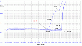
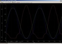
Enclosed one can see a simulated THD% graph for 3 different
resistive load : 6,4,3 Ohm. the figure shows a very good
behavior but for the last case where we see the switching artifacts.
clipping power respectively about: 107,160,190 Wrms.
Nevertheless, the 9+ remain a very good amp, axpecially
considering the age of the design.
And, definitely, it has no sudden switch point from class-A to class-AB which causes audible distortions (and then, output device never switch off, so it is difficult to speak about Class AB)
Sure, it is not a pure class A amplifier and we can see this from
the low value of quiescent current (1 A= 5X200mA), but the double diode circuit which govern the dynamic class A operation has a very smooth behavior. I rarely have listened (my opinion, obviouly) at amp better than the 9+
dispite its very slow price.
bye
Federico
The Sumo amp is limited from about 40 (nine) to about 70 (nine+) Watts rms (4 Ohm)
only due to its inherent structure.
I can not say about the 9. The 9+ deliver 65 W (8 Ohm ) as nominal power.
One can easily measure 80 Wrms (8 Ohm) and 160 Wrms (4 Ohm) before clipping, that is
voltage difference with a peak to peak value of about 72 Volts.
The liming factor is in the Opamp dual supply of about +-21/22 Volts (then will come
the 45 V floating supply). Drop this value
and the power will drop too and viceversa.
The very good near constant slope of the harmonic spectral curves of
the new Thorens amp would never be possible with the Sumo amp structure.
The Sumo 9+ THD curve has a near constant value on both 8 Ohm and 4 Ohm.
For load value below these I'll say later (see attached graph from simulatio).
Speaking about simulations, are you sure to utilize the correct schematics?
I advice you to refer here
http://www.geocities.com/fscarpa58/schematics/nine_plus.pdf
My amp delivers 60W rms at 4 ohms and 95W rms at 8 ohms only.
May be you have exchanged 8 and 4 Ohm and these appear data coming from an incorrectly biased 9 and not from a proper set up 9+.
The available output power strongly depends on the
current gain of the output transistors and on the
transfer characteristic of these transistors and
verys from amp to amp.
I own two 9+ and they perform identical. I mean
electrically, meausered at my lab.
Bongiorno discovered that and added the very clever
designed additional current circuit including 2 pnp
small signal transistors. These transistors add (switch!)
a third current path at an output power of about 10W rms at 4 ohms.
If correctly set up and if no fake devices, the npn pair remains OFF at both 8 and 4 Ohm irrespective of the power.
They switch ON only with smaller loads (3 Ohm at 120 W)
Bongiorno added that trick to 9+ to increase the ability of
the old 9 to drive low impedence. Unfortunately this happens
at a price of increased distortion, expecially of high order,
due to the switching process. So the 9+ is not suitable
in case of load smaller than 4 Ohm.
Enclosed one can see a simulated THD% graph for 3 different
resistive load : 6,4,3 Ohm. the figure shows a very good
behavior but for the last case where we see the switching artifacts.
clipping power respectively about: 107,160,190 Wrms.
Nevertheless, the 9+ remain a very good amp, axpecially
considering the age of the design.
And, definitely, it has no sudden switch point from class-A to class-AB which causes audible distortions (and then, output device never switch off, so it is difficult to speak about Class AB)
Sure, it is not a pure class A amplifier and we can see this from
the low value of quiescent current (1 A= 5X200mA), but the double diode circuit which govern the dynamic class A operation has a very smooth behavior. I rarely have listened (my opinion, obviouly) at amp better than the 9+
dispite its very slow price.
bye
Federico
Attachments
Hallo federico,
first you are right, I have made a typing error with that 4 and 8 Ohm load, that have to be exchanged.
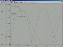
I used your schematic for simulation and for comparing the results I used the same reference designators as you. I attache one diagram here and the other in the following post. One can see that the output current is limited and the switching behaviour is clearly seen as well. The load for this simulation is 4 ohms.
first you are right, I have made a typing error with that 4 and 8 Ohm load, that have to be exchanged.
I used your schematic for simulation and for comparing the results I used the same reference designators as you. I attache one diagram here and the other in the following post. One can see that the output current is limited and the switching behaviour is clearly seen as well. The load for this simulation is 4 ohms.
Attachments
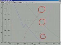
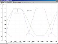
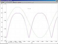
and here is a more detailed view onto the switching behaviour. Note the output voltage at about 9 Volts when switching occurs. That equals to about 10 Watts rms (4 Ohm load used). Sorry for the bad picture quality. I had to compress the image.
Attachments
Hi Arcolette
Sim completely different from mine!
have you set R41 = 150 Ohm ? ( the sliding bias resistor
connected the two diodes)
I ask for this since I noticed that the number was not there.
I fix this only today.
Something wrong is happening since current have a completely
different behavior.
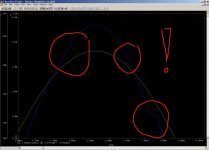
see figure (sorry for the scaling)
bye
Federico
note: nec 2sd555 are best simulated with ON MJ15022
Sim completely different from mine!
have you set R41 = 150 Ohm ? ( the sliding bias resistor
connected the two diodes)
I ask for this since I noticed that the number was not there.
I fix this only today.
Something wrong is happening since current have a completely
different behavior.
see figure (sorry for the scaling)
bye
Federico
note: nec 2sd555 are best simulated with ON MJ15022
Attachments
Hallo Federico,
I cannot find the R41 on my schematic. Do you mean R38? That is the resistor which is connected between the diodes and ground on your schematic. In your former posted schematic it had a value of 1k. I changed it to 150R and made a new simulation. My results does not fit yours. But it meets an analytical analysis / calculation. And the switching distortion still exists (see second picture in the next post). I hope we could find out the difference.
I cannot find the R41 on my schematic. Do you mean R38? That is the resistor which is connected between the diodes and ground on your schematic. In your former posted schematic it had a value of 1k. I changed it to 150R and made a new simulation. My results does not fit yours. But it meets an analytical analysis / calculation. And the switching distortion still exists (see second picture in the next post). I hope we could find out the difference.
Attachments
Hi Arcolette
yes, yes ... R38
Strange, I obtain your identical result only if I set R38 equal to
300.
first of all check the whole circuit for mistakes since there was
some. But I do not think this is the problem.
There is a possibility, maybe you have implemented the circuit
(diodes and res.) according to the original patent from J.Bongiorno. in that patent each diode has its resistor.
And, always maybe, you have set each resistor to 300 thinking
that they were equivalent to a single res of 150 Ohm.
It is not so, since the paths are mutual exclusive the value has to be set to 150 each also in case of two resistor.
However, there is a way to calibrate the circuit. From your current
plot it appears that each output BJT has an average power dissipation
of about 12-13 W ( 4 Ohm load and amplitude of the output
of about 21V) vs. a static dissipation of about 9W (45X200mA)
Well, decrease the value of R38 to obtain an average dissipation of about 25W.
This is the right setup.
Let me know
Federico
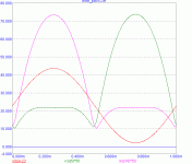
Hallo Federico,
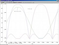
I double checked my schematic - it is identical to yours. I made some new simulations to find out the cause of our different simulation results. I guess I have found it: The current curves of the output transistors strongly vary with the load. My simulation with 8 Ohm load shows nearly the same behaviour as your simulation. If the load is not present, the currents rise up. And finally I get my previous results with 4 Ohm load. I used an input signal of 3Vpp for driving the amp to clipping levels just for getting an idea about the max. available power. That is about 96 Wrms for 4 Ohm load and about 64 Wrms for 8 Ohm load and fits my own measurements (see the following pictures).
Keeping in mind that a real loudspeaker has a quite large variation of the impedance over frequency the current transfer characteristic of the output stage varies a lot. Again, the Sumo amp was a real great design at its time, but I avoid any switching effects or characteristic variation of the amp.
Here is the 4 Ohm diagram:
Attachments
well Arcolette
there are to distinct uncorrekated point.
first the max amplitude of output signal on your sim
results to be about 32 Volts (hence 64W) while in my
sim it is about 36V (80W).
This is only due to the opamp device in two way
1) supply voltage : I have +- 21.5 since I measured
these values in both my amp (along with a float of 47 Volts)
2) opamp model
Then there is the switching problem.
It is not a problem of load. Yes I know that changing the load
you have a completely different behavior, the amp id designed so.
Rather, it is like you have a 300 Ohm resistor. I don't figure out why but try to set your resistor to 75 Ohm andlook at the results.
maybe this is only the result of different model.
As I said you, the only possible procedure is to set up correctly the amp based on the performance.
This is another methos more simple than the previous:
-set the load to 4 Ohm.
-set R38 very low in such a way the devices never cut off.
-go to the clipping condition (32 Volts or better if you succeded
in rise that value to 35-36V)
-start rising the value of r38. the central part of the current
will decrease. go on rising and stop when at the threshold of cut off.
now the amp is correctly set up.
Federico
Does anybody know a replacement for the MPSu55 that's used in the Sumo Nine.?
sdman
try the NTE189 (or EGC189)
Federico
Attachments
Would be interesting to see the schematic of the Thorens
TEM3200. I see that they are using a driver xfm on the input side.
This way they get complete isloation.
Would like to see the translated version mentioned in post #76.
sdman
P.S. I used an on-line translator but it was with mixed results.
TEM3200. I see that they are using a driver xfm on the input side.
This way they get complete isloation.
Would like to see the translated version mentioned in post #76.
sdman
P.S. I used an on-line translator but it was with mixed results.
sdman said:Does anybody know a replacement for the MPSu55 that's used in the Sumo Nine.?
sdman
I guess that BD526/528/530 from Motorola would fit nicelly.
Best, Ivo
Originally posted by sdman
Does anybody know a replacement for the MPSu55 that's used in the Sumo Nine.?
sdman
BD238
SK3200
2SA818
from an equivalences search
hope this help
Federico
Jan Dupont;278913 post #10 said:Some CROWN amps has the same...
")
Interesting. Please let me know some models - thank you.
here a circlotron circuit:
http://www.amplimos.it/images/CIRCLOTRON_50W.bmp
BTW - who knows the currently link from
http://www.audio-circuit.dk/images/schematics/Sumo-Andromeda-ll-pwr-sch.pdf ??
Last edited:
tief;Interesting. Please let me know some models - thank you.
That was back in 2003
I don't recall the models, but you can do a search on their Legacy amp pages
- Status
- This old topic is closed. If you want to reopen this topic, contact a moderator using the "Report Post" button.
- Home
- Amplifiers
- Solid State
- SUMO Power Amp