Davidsrsb, greetings! My Luxman L435 amplifier suddenly failed, many transistors and the STK3102 Mark3 hybrid assembly burned out. Could you share the project for Kicad so that I can make small adjustments myself, specifically for myself and based on the results of modeling the power amplifier of this amplifier in Microcap. Thank you very much!
Can you explain in more detail what you are writing about here?For the network that is used to bias the ips and vas you could replace a resistor with a constant current source such as S-102, chose resistors for about 20v across the CCS diode
Good idea removing the mask on the rear on a FR4 version.Hi,
I built your -c version using FR4 and chose the thinner dielectric thickness. If the dielectric is the same thickness I do not see a reason to use the aluminum backed tech vs regular fr-4.
On the fr-4 design you could remove the solder mask on the back side, have it tin or even gold plated. Removing the SM would allow for better cooling.
For the network that is used to bias the ips and vas you could replace a resistor with a constant current source such as S-102, chose resistors for about 20v across the CCS diode
I also found when I reviewed the design and soldered it up that I think you could get away with using 0805 sized parts but I would need to do the layout to verify if it’s possible.
I have yet to test the version you built along with a stk-0050-II that recently designed.
The S-102 is 100V absolute maximum, so not suitable for many uses of this module, not so easy to buy either.
I used a 0603 footprint with large pads to allow hand soldering and to dump heat better. SMD parts radiate very little heat directly from the package
May be, you placed on PCB 0805 3x 18K instead 0603 and put this correct Gerber, because you don't want to give files of Kicad project.I am reworking this design in KiCad V8. This has brought up a limitation in KiCad, that it cannot design aluminium (IMS) backed boards accurately.
This means selecting the correct Gerber layers only and explaining to JLCPCB what you want carefully.
It’s not going to see the full supply voltage across it, you still need the two resistors (~18k) in series with it to bring the voltage to ~20V across it.The S-102 is 100V absolute maximum, so not suitable for many uses of this module, not so easy to buy either.
The part is available at Mouser.
I do not use kicad but I do not see why it has a problem with the metal backed pcb, what is essentially a single sided pcb.
Thaks! Additional I be want add resistor local feedback in 0805 size between emiter Q7 and base Q2, you are correct gerber files for this or not. If yes, then put files with this local feedback. ThanksTry these files, based on KiCad V8 and with 0805 size for the bias chain
Mouser is not so easy to use outside the US. The voltage you need to drop depends on the amplifier rails. Also note that there is quite a spread on the nominal 1 mAIt’s not going to see the full supply voltage across it, you still need the two resistors (~18k) in series with it to bring the voltage to ~20V across it.
The part is available at Mouser.
Adding that feedback is tricky without going to additional layers, there are a couple of tracks to get past.Thaks! Additional I be want add resistor local feedback in 0805 size between emiter Q7 and base Q2, you are correct gerber files for this or not. If yes, then put files with this local feedback. Thanks
There are variants of the Sanyo module with feedback resistors, but they are bought out on extra pins and require connection on the main PCB. They are not connected internally on the PCB to these transistors
The CRD has sufficient compliance to deal with the variations in supply V and current tolerance.Mouser is not so easy to use outside the US. The voltage you need to drop depends on the amplifier rails. Also note that there is quite a spread on the nominal 1 mA
Getting the CRD part is probably no different than getting the rest of the semis. It’s an option so you can either use the resistor or the CRD. I would think that the CRD option would allow for a better PSRR.
One other option I can think of is to add emitter resistors for the LTP inputs. Looks to be enough room to fit them in
Good luck
Put in emitter resistors and you have a different amplifier. These Sanyo modules were all about low headline THD by the use of high open loop gain, sacrificing some stability and overload behaviour.
This project is about creating a clone to keep old amplifiers out of landfill.
If I wanted to improve the amplifier, I would start by adding more fault detection. There is generally a lack of short circuit and SOAR protection circuitry
This project is about creating a clone to keep old amplifiers out of landfill.
If I wanted to improve the amplifier, I would start by adding more fault detection. There is generally a lack of short circuit and SOAR protection circuitry
I'm grateful for input. I just wonder how the improved PSRR of putting in a CRD might change the sound signature of the amplifier. Unintended consequences.No problem, carry on, mind my input
What I do need is more info on the dimensions of the modules, their heatsinking, mounting and space around them.
Have fun...try datasheetcatalag.com, and other similar sites.
Sanyo Semiconductor is gone, taken over by OnSemi I think.
I am getting a too big file message, so I deleted the file I had which described different STK modules.
Search for STK audio modules, there were SMPS controllers and motor drives also among other things in that series.
Sanyo Semiconductor is gone, taken over by OnSemi I think.
I am getting a too big file message, so I deleted the file I had which described different STK modules.
Search for STK audio modules, there were SMPS controllers and motor drives also among other things in that series.
These resistors will only reduce the loop gain as I understand it!Put in emitter resistors and you have a different amplifier. These Sanyo modules were all about low headline THD by the use of high open loop gain, sacrificing some stability and overload behaviour.
You only changed to 0805 R7,R10, R11 but not change R27, R30, R31, please change this and put new gerbers.
Please explain, better even graphically, what rsavas writes about CRD, LTP, the purpose of the 56k (18k x3) resistor and how it is calculated or selected? How can you improve the stability of amplifiers based on STK3102 mark3, so as not to burn out expensive transistors in the future?
Please explain, better even graphically, what rsavas writes about CRD, LTP andhow this can improve the performance of the amplifier?No problem, carry on, mind my input
What I do need is more info on the dimensions of the modules, their heatsinking, mounting and space around them.
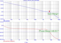
about stability on pahase normal, but on amplitude only 4,6 dB
Attachments
Last edited:
The input transistor run at about 1 mA each. This gives a gm of about 20mA/VThese resistors will only reduce the loop gain as I understand it!
You only changed to 0805 R7,R10, R11 but not change R27, R30, R31, please change this and put new gerbers.
The open loop gain is badly defined as the load depends on the Hfe of Q5
Adding emitter resistors reduces the gm and improves open loop linearity.
Why do you want 0805 resistors, the dissipation is tiny?
- Home
- Design & Build
- Parts
- STK3152/STK3102 Clone for aluminium back PCB