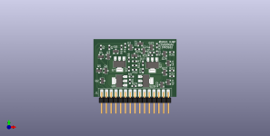
This is a variation of my clone STK3102 intended for an aluminium backed PCB
It uses a pin header as a SMD connector.
I had to extend the board slightly to allow enough pad to solder the connector
If this is OK, I will post the Gerber files as a charity donation project again
It uses a pin header as a SMD connector.
I had to extend the board slightly to allow enough pad to solder the connector
If this is OK, I will post the Gerber files as a charity donation project again
Attachments
That looks great, I have seen through hole attempts in the past for replacement, but never SMD! Is this supposed to fit the housing of the STK parts ?This is a variation of my clone STK3102 intended for an aluminium backed PCB
It uses a pin header as a SMD connector.
I had to extend the board slightly to allow enough pad to solder the connector
If this is OK, I will post the Gerber files as a charity donation project again
This is what I am asking, I don't have any of the amplifiers around.That looks great, I have seen through hole attempts in the past for replacement, but never SMD! Is this supposed to fit the housing of the STK parts ?
This board is 44.5mm x 31.1mm, compared with my THT connector version which is 44.5mm x 30.5mm
")
I do have an amplifier with 1 shot STK channel somewhere which I would have to unsolder, but I am pretty sure someone else on here has a STK module inreach to give you the dimensions to crosscheck!This is what I am asking, I don't have any of the amplifiers around.
This board is 44.5mm x 31.1mm, compared with my THT connector version which is 44.5mm x 30.5mm
How thick is that aluminum backed board? If it’s “thin” enough to sandwich between double row headers the second row can be glued to the aluminum backplane, giving it more mechanical support and making it less likely you’ll peel the pads off the board. Trim the back row off once it’s mounted if you‘re putting it in an existing device, leave them there for new construction where you’re making the motherboard anyway. I do this sort of mounting with double sided boards all the time, and it’s quite robust. .062 fits in between the rows quite nicely.
I would also suggest mounting ears on the sides, so it can be attached to a real heat sink (an old pentium CPU cooler comes to mind). One of the weaknesses of these things is heat transfer - going thru thermal vias to a backplane is already a disadvantage, so any help you can give it will make it last that
much longer.
The curved parts at the sides of the STK modules had holes for mounting screws to pass through, at least most did.
That was to attach them to the heat sink. Thermal paste in a thin layer to be used.
Met my car electrician, he was telling me the new cars have LED headlights with heat sinks and cooling fans...the fans fail, and the LED dies due to heat, the entire lamp has to changed. Expensive.
A new source of heat sinks and fans for us DIYers?
Gerbers and PDFs of layers. This is a single sided version for aluminium backed PCB, so there are no B side layers and no drill files.
As always this is a charity donation project. Anyone who uses these files, please make a donation to a charity of your choice.
As always this is a charity donation project. Anyone who uses these files, please make a donation to a charity of your choice.
Attachments
Hello davidsrsb!
I found this forum with a question about how to replace 3102 IV, I'm from Russia, can you help me buy a ready-made v2022 board, or a board without smd, but with a complete list of all smd parts,
I can't find a list of smd parts that need to be mounted to the board.
Thanks in advance davidsrsb
text google translate
Thanks davidsrsb!
I downloaded the file, now I'll try to figure it out, all this will probably drag on for more than one month,
so I'll thank you for your help later, but don't hesitate! Write in a private message the amount of the donation.
Thanks in advance .
Google Translate
I downloaded the file, now I'll try to figure it out, all this will probably drag on for more than one month,
so I'll thank you for your help later, but don't hesitate! Write in a private message the amount of the donation.
Thanks in advance .
Google Translate
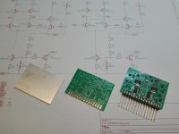
Great job !My progress so far...
Can anyone please help me with ordering these boards? I’m pulling my hair out! I’m very new to ordering, I ordered one other set of boards like 4 years ago.
I took the gerber file that is in post 10 from David (thank you David, a donation will be made in your honor to a local food bank!) and put it in the “add gerber file” section on JLCPCBs webpage.
It gave me this screen, and since it wasn’t automatically set to aluminum and on FR4 I thought maybe it did it wrong.

So I switched it to aluminum, but it says it’s a 2 layer board and the dimensions are not populated.

Everything else is pre selected and won’t let me change it, except quantity (15 probably) and thickness (1.6 the way to go, or is 1.0 or 1.2 the way to go with aluminum back PCBs?).


And it won’t let me save anything to my cart. Am I supposed to put in the dimensions myself? I figured those would be auto populated. Recommendations as to what to pic for the other fields? Any help would be extremely appreciated!!! I’ll make my donation in honor of those that help me too! Thank you so much,
Dan
I took the gerber file that is in post 10 from David (thank you David, a donation will be made in your honor to a local food bank!) and put it in the “add gerber file” section on JLCPCBs webpage.
It gave me this screen, and since it wasn’t automatically set to aluminum and on FR4 I thought maybe it did it wrong.
So I switched it to aluminum, but it says it’s a 2 layer board and the dimensions are not populated.
Everything else is pre selected and won’t let me change it, except quantity (15 probably) and thickness (1.6 the way to go, or is 1.0 or 1.2 the way to go with aluminum back PCBs?).
And it won’t let me save anything to my cart. Am I supposed to put in the dimensions myself? I figured those would be auto populated. Recommendations as to what to pic for the other fields? Any help would be extremely appreciated!!! I’ll make my donation in honor of those that help me too! Thank you so much,
Dan
- Home
- Design & Build
- Parts
- STK3152/STK3102 Clone for aluminium back PCB