oh yeah.....
the older stks are obsolete,
still stks being made like 412-070 etc
some still being developed,
mostly other large companies like pioneer and kenwood and sony are custom ordering stks to suit their current line recievers, subs etc.
there are very much discrete style stks (STK20*8) series 21** and 22*0 series (2ch darlington configs) that have collector inputs and common or split emitter out - though not all were complimentry symmetry
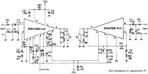
STK 4152 Schematic
STK 4152 / 2*30Watt can be Bridge?
I want to ask with anyone,
i have stk 4152 chip, stereo 2X30 watt. from my sony ampifier
can i bridge this chip so i can use 60 watt Power amply/ 30+3-0 watt.
need advise an info.
sorry about my english is not good
this is the schematic of STK 4152
thx
this is the schematic
Attachments
STK Kits
Greetings fellow STK fans!
I bought an amplifier kit that uses the STK401-040 last saturday.
Took 1 hour to assemble it on a sunday afternoon! Its a 25W+25W RMS amplifier.
I was amazed to the sound I heard coming out from my speakers, TDL Electronic's RTL3. The bass is deep and thick. The control is excellent, the staging is wide and big. I also have a TA2024 amp. I'd say it is as good but better (louder!). Whatever the T-Amp can do, so did the STK.
I also found that my local electronic stores still have a number of STK modules for sale! Initially I was planning to build a GainClone (LM3886), but now that I have the STK, goodbye GainClone!
Need to stock up a few before they run out...")
I am now a confirmed STK fan!
Have fun guys, I know I am..
Greetings fellow STK fans!
I bought an amplifier kit that uses the STK401-040 last saturday.
Took 1 hour to assemble it on a sunday afternoon! Its a 25W+25W RMS amplifier.
I was amazed to the sound I heard coming out from my speakers, TDL Electronic's RTL3. The bass is deep and thick. The control is excellent, the staging is wide and big. I also have a TA2024 amp. I'd say it is as good but better (louder!). Whatever the T-Amp can do, so did the STK.
I also found that my local electronic stores still have a number of STK modules for sale! Initially I was planning to build a GainClone (LM3886), but now that I have the STK, goodbye GainClone!
Need to stock up a few before they run out...
I am now a confirmed STK fan!
Have fun guys, I know I am..
STK3102
Has anyone ever used these as per the 'test circuit' in the datasheet?
http://www.ortodoxism.ro/datasheets/sanyo/STK3122.pdf
Andy
Has anyone ever used these as per the 'test circuit' in the datasheet?
http://www.ortodoxism.ro/datasheets/sanyo/STK3122.pdf
Andy
STK 459 going strong for 30 years so far. About two decades of its duty was around-the-clock nonstop operation.
It has been replaced by a Tripath with switcher supply, because of energy consumption.
The STK still works perfectly.
It is available on ebay as Technics SA80
I'm currently attempting to build a discrete STK amp, just for fun. It seems that it takes only a bit more time to solder than a chip amp.
It has been replaced by a Tripath with switcher supply, because of energy consumption.
The STK still works perfectly.
It is available on ebay as Technics SA80
I'm currently attempting to build a discrete STK amp, just for fun. It seems that it takes only a bit more time to solder than a chip amp.
Re: STK3102
these circuits found their way in mostly sansui amplifiers where driving a pair of jap transistors ....
sound was average i think ..... i am actually surprized of so many people here think that stk sounds good ..... ( !!!!) but then again i forgot i was in the chip forum .....
about the 3122 family as isaid the sound was average but the most serious was stability since if amps were pushed to the edge most of the time failed .....
on the other hand for easy casual listening was a simple solution ....
regards sakis
poynton said:Has anyone ever used these as per the 'test circuit' in the datasheet?
http://www.ortodoxism.ro/datasheets/sanyo/STK3122.pdf
Andy
these circuits found their way in mostly sansui amplifiers where driving a pair of jap transistors ....
sound was average i think ..... i am actually surprized of so many people here think that stk sounds good ..... ( !!!!) but then again i forgot i was in the chip forum .....
about the 3122 family as isaid the sound was average but the most serious was stability since if amps were pushed to the edge most of the time failed .....
on the other hand for easy casual listening was a simple solution ....
regards sakis
Re: Re: STK3102
I remember that, at the time, the Technics SA80 (STK 459) had clearer bass and an overall clearer sound than most of its competition. Even today, it does a good job as a "medium" reference, and surpasses the qualities found on the mass market today.
So, perhaps its not the highest fidelity available. However, that SA80 was ahead of its peers and still is.
The flaws are similar to some transistor amps, and also evident in ST Thompson amplifiers. The bass isn't as tight as a high fidelity grade amplifier. For super-stiff ported box drivers, its unnoticeable. However, rather floppy sealed box speakers could "boom" terribly.
I think its possible that this is related to its tone controls and its power circuit, thus also possible it had nothing to do with the STK 459 itself. I don't know and won't find out, as I am not going to disassemble the SA 80. Its my speaker test amp. And, I use its little flaw as a diagnostic tool.
Come to think of it, this amp has clear baritones, despite its little bass issue. This gives it a warm, old fashioned, flair, but it still plays clear. Its rich presentation is almost a "have your cake and eat it too" scenario, and therein is a reason to like STK.
Another reason is the level frequency response (distortion doesn't rise with frequency during the audio band), despite a wide variety of configurations. This is an unusual "bulletproof" feature in a chip amp, quite suited to "tubefake" era units like the SA80.
This STK being "a medium reference" means that there's room for improvement, and, although doable, its not easy.
sakis said:. . .
sound was average i think ..... i am actually surprized of so many people here think that stk sounds good ..... ( !!!!) but then again i forgot i was in the chip forum .....
. . .
I remember that, at the time, the Technics SA80 (STK 459) had clearer bass and an overall clearer sound than most of its competition. Even today, it does a good job as a "medium" reference, and surpasses the qualities found on the mass market today.
So, perhaps its not the highest fidelity available. However, that SA80 was ahead of its peers and still is.
The flaws are similar to some transistor amps, and also evident in ST Thompson amplifiers. The bass isn't as tight as a high fidelity grade amplifier. For super-stiff ported box drivers, its unnoticeable. However, rather floppy sealed box speakers could "boom" terribly.
I think its possible that this is related to its tone controls and its power circuit, thus also possible it had nothing to do with the STK 459 itself. I don't know and won't find out, as I am not going to disassemble the SA 80. Its my speaker test amp. And, I use its little flaw as a diagnostic tool.
Come to think of it, this amp has clear baritones, despite its little bass issue. This gives it a warm, old fashioned, flair, but it still plays clear. Its rich presentation is almost a "have your cake and eat it too" scenario, and therein is a reason to like STK.
Another reason is the level frequency response (distortion doesn't rise with frequency during the audio band), despite a wide variety of configurations. This is an unusual "bulletproof" feature in a chip amp, quite suited to "tubefake" era units like the SA80.
This STK being "a medium reference" means that there's room for improvement, and, although doable, its not easy.
Speedskater said:I have two (maybe 3) Fisher PA 301 chips up in the attic. My 1985 receipt lists them as Sanyo chips.
Cool Speedskater!
You could see if they have the "loudness" button done with resistor padding and a cap per channel, and if there's the weird Japanese style balance control arrangement. Those two things are the worst distortions from the amplifiers of that era. I think it works to "patch in" at the output of the volume control, which, typically, leaves the bass-n-treble controls and the pre all functional.
If a source plays nicely that way (check first for DC), you can possibly patch from lineout to a brand new volume control. That will knock out the balance control and loudness button on most older Japanese transistor/chip receivers.
Check the service manual. Maybe a slight mod will have those up to nearly hi-fi.
Re: STK Kits
I agree STK chips sound great!!!!
jazzy939 said:Greetings fellow STK fans!
I bought an amplifier kit that uses the STK401-040 last saturday.
Took 1 hour to assemble it on a sunday afternoon! Its a 25W+25W RMS amplifier.
I was amazed to the sound I heard coming out from my speakers, TDL Electronic's RTL3. The bass is deep and thick. The control is excellent, the staging is wide and big. I also have a TA2024 amp. I'd say it is as good but better (louder!). Whatever the T-Amp can do, so did the STK.
I also found that my local electronic stores still have a number of STK modules for sale! Initially I was planning to build a GainClone (LM3886), but now that I have the STK, goodbye GainClone!
Need to stock up a few before they run out...
I am now a confirmed STK fan!
Have fun guys, I know I am..
I agree STK chips sound great!!!!
Re: STK Kits
Very interesting service manual for STK 465, showing things done right. Its amazing. How to ac couple the nfb a bit more cleanly (drive first the cap), and how to get along without a bootstrap cap like ST uses for TDA7294 (use a resistor instead).
There's a lot of STK 457, 459, 460, 461, 463, 465 showing up on E-bay. Some state Generic, some don't say, and some say Authentic Sanyo.
The current model 465, substitutes for 461, 463 too, as there is no internal difference in the 3 higher power models. The 465 does 30w per channel at 0.08% distortion, yet the 1% figure is higher than the mechanical limits of most 8" and 10" drivers.
Interesting for DIY, using a $28, 4 amper, Hammond EI core 36vct (18+18vac) transformer with 465 will downrate it to a 463, resulting in 25 clean watts per channel on 8 ohms; however, a peak rating would be 200w combined output if given 4 ohm speakers (as modern amplifiers are advertised). http://www.mcmelectronics.com/product/STK465
Kind of spendy, but you get some authentic tunes this way.
But, if you need more. . .
There's also this: http://www.mcmelectronics.com/product/STK4231V closely related chip with 100 watts per each of 2 channels, while THD = 0.08%. In other words its 100w per channel, effortlessly. The peak rating is beyond the mechanical limits of most speaker drivers. As with most amplifiers, for 4 ohm speaker support, decrease the voltage, and double the heatsink, whenever the possibility of 4 ohm speakers are expected.
Also, check out NE5534 at Decibel Dungeon.
STK + good power supply + a bit of fine tuning + a good buffer/pre = JAW DROP
jazzy939 said:Greetings fellow STK fans!
I bought an amplifier kit that uses the STK401-040 last saturday.
Took 1 hour to assemble it on a sunday afternoon! Its a 25W+25W RMS amplifier.
I was amazed to the sound I heard coming out from my speakers, TDL Electronic's RTL3. The bass is deep and thick. The control is excellent, the staging is wide and big. I also have a TA2024 amp. I'd say it is as good but better (louder!). Whatever the T-Amp can do, so did the STK.
I also found that my local electronic stores still have a number of STK modules for sale! Initially I was planning to build a GainClone (LM3886), but now that I have the STK, goodbye GainClone!
Need to stock up a few before they run out...
I am now a confirmed STK fan!
Have fun guys, I know I am..
Very interesting service manual for STK 465, showing things done right. Its amazing. How to ac couple the nfb a bit more cleanly (drive first the cap), and how to get along without a bootstrap cap like ST uses for TDA7294 (use a resistor instead).
There's a lot of STK 457, 459, 460, 461, 463, 465 showing up on E-bay. Some state Generic, some don't say, and some say Authentic Sanyo.
The current model 465, substitutes for 461, 463 too, as there is no internal difference in the 3 higher power models. The 465 does 30w per channel at 0.08% distortion, yet the 1% figure is higher than the mechanical limits of most 8" and 10" drivers.
Interesting for DIY, using a $28, 4 amper, Hammond EI core 36vct (18+18vac) transformer with 465 will downrate it to a 463, resulting in 25 clean watts per channel on 8 ohms; however, a peak rating would be 200w combined output if given 4 ohm speakers (as modern amplifiers are advertised). http://www.mcmelectronics.com/product/STK465
Kind of spendy, but you get some authentic tunes this way.
But, if you need more. . .
There's also this: http://www.mcmelectronics.com/product/STK4231V closely related chip with 100 watts per each of 2 channels, while THD = 0.08%. In other words its 100w per channel, effortlessly. The peak rating is beyond the mechanical limits of most speaker drivers. As with most amplifiers, for 4 ohm speaker support, decrease the voltage, and double the heatsink, whenever the possibility of 4 ohm speakers are expected.
Also, check out NE5534 at Decibel Dungeon.
STK + good power supply + a bit of fine tuning + a good buffer/pre = JAW DROP
Hi daniel,
Some questions here, related to your posting..
What is meant by a 'good power supply' really?
Currently I am driving my STK amp via a simple JFet pre/buffer, which make the sound really excellent!
I am blur on the 'fine tuning' part.. any clues?
Thanking you in advance..
Some questions here, related to your posting..
What is meant by a 'good power supply' really?
Currently I am driving my STK amp via a simple JFet pre/buffer, which make the sound really excellent!
I am blur on the 'fine tuning' part.. any clues?
Thanking you in advance..
Fine tuning, start with power
That's one heck of a question.
The fine tuning is about the same for any amplifier in that you start in the same place.
Its not the input circuit.
Its not the NFB.
Its not the pre.
Actually, you do need those functional; but, at first, you just "rough them in" with "known good" components or whatever you favor / have on hand.
The main effort for fine tuning is at the power circuit:
Here is where you can get your low bass notes.
Here is where you can either cause or prevent ringing midbass.
Here is where you can get your audio upper midband both slightly euphonic and also clear.
And, some of your power circuit decisions can affect the heat output of the amplifier.
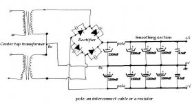
I like to view the power circuit as three seperate boards:
Rectifier board
Power supply board
Amplifier board
I like to see these connected so that there are "poles" between, and we can use either a resistor or an interconnect cable to establish a pole.
Assumptions:
The amplifier isn't bridged
The power supply is linear unregulated
Not everyone owns very huge speakers and those that do might like to hear them do their thing.
Many chip-amps of all sorts, are slightly bass shy from 20hz to 50hz
The STK chip that we're using is a model that pre-dates "modernized" (fictional) power output advertisements.
Rectifier board:
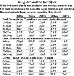
Common choices for transformer are 4a, 6a, 8a.
Most of our STK application notes will call for the 4a, but may I encourage you to go "1 step up" and get a "generous" amperage transformer, if budget allows? In the linear, unregulated power supply that's one sure-fire way to get some good bass and avoid the typical midbass issues. As for midbass, its so much easier to cause it than remove it. Like a bell, the larger size transformer rings a lower pitch. Like a loudspeaker's crossover, the power supply is a filter for the transformer.
Sure, you do have the option of using a purposefully overlarge dual-secondaries toroid transformer and eight of MUR860, but, I'm not promoting that, as it doesn't match the classic applications.
However, the classic applications of these STK used EI core, and most of them were center tap:
From the service manuals of the original amplifiers, we can see large ceramic caps at the rectifier. While 3-pin ceramic caps are rare, we can do the same job with regular ceramic caps. They'll need to be physically large, such as almost 1cm across the disc (although smaller physical sizes can work). This is incompatible with soft switch diodes, so use regular diodes or a 1 piece bridge block, like the currently popular KBPC2504.
Before giving the sizing chart, I'd like to reference the CarlosFM power supplies:
One way to get enhanced bass from the amplifier is to locate a pair 4700uF caps at DC side of the rectifier board. If you get too much bass, just size down a bit to 3300uF. One or two pair of Cornell-Dublier's Mallory SEK 50v 2200uF is also an option. The rectifier board is where you put the "bassy" caps. This disturbance is a signal and so, it belongs close to the rectifier, if anywhere at all. Later, our power supply board will be able to smooth it out to cleaner DC.
Here's the chart for paralleling small caps to your diodes at the rectifier board (click on picture):
jazzy939 said:Hi daniel,
Some questions here, related to your posting..
What is meant by a 'good power supply' really?
Currently I am driving my STK amp via a simple JFet pre/buffer, which make the sound really excellent!
I am blur on the 'fine tuning' part.. any clues?
Thanking you in advance..
That's one heck of a question.
The fine tuning is about the same for any amplifier in that you start in the same place.
Its not the input circuit.
Its not the NFB.
Its not the pre.
Actually, you do need those functional; but, at first, you just "rough them in" with "known good" components or whatever you favor / have on hand.
The main effort for fine tuning is at the power circuit:
Here is where you can get your low bass notes.
Here is where you can either cause or prevent ringing midbass.
Here is where you can get your audio upper midband both slightly euphonic and also clear.
And, some of your power circuit decisions can affect the heat output of the amplifier.
I like to view the power circuit as three seperate boards:
Rectifier board
Power supply board
Amplifier board
I like to see these connected so that there are "poles" between, and we can use either a resistor or an interconnect cable to establish a pole.
Assumptions:
The amplifier isn't bridged
The power supply is linear unregulated
Not everyone owns very huge speakers and those that do might like to hear them do their thing.
Many chip-amps of all sorts, are slightly bass shy from 20hz to 50hz
The STK chip that we're using is a model that pre-dates "modernized" (fictional) power output advertisements.
Rectifier board:
Common choices for transformer are 4a, 6a, 8a.
Most of our STK application notes will call for the 4a, but may I encourage you to go "1 step up" and get a "generous" amperage transformer, if budget allows? In the linear, unregulated power supply that's one sure-fire way to get some good bass and avoid the typical midbass issues. As for midbass, its so much easier to cause it than remove it. Like a bell, the larger size transformer rings a lower pitch. Like a loudspeaker's crossover, the power supply is a filter for the transformer.
Sure, you do have the option of using a purposefully overlarge dual-secondaries toroid transformer and eight of MUR860, but, I'm not promoting that, as it doesn't match the classic applications.
However, the classic applications of these STK used EI core, and most of them were center tap:
From the service manuals of the original amplifiers, we can see large ceramic caps at the rectifier. While 3-pin ceramic caps are rare, we can do the same job with regular ceramic caps. They'll need to be physically large, such as almost 1cm across the disc (although smaller physical sizes can work). This is incompatible with soft switch diodes, so use regular diodes or a 1 piece bridge block, like the currently popular KBPC2504.
Before giving the sizing chart, I'd like to reference the CarlosFM power supplies:
One way to get enhanced bass from the amplifier is to locate a pair 4700uF caps at DC side of the rectifier board. If you get too much bass, just size down a bit to 3300uF. One or two pair of Cornell-Dublier's Mallory SEK 50v 2200uF is also an option. The rectifier board is where you put the "bassy" caps. This disturbance is a signal and so, it belongs close to the rectifier, if anywhere at all. Later, our power supply board will be able to smooth it out to cleaner DC.
Here's the chart for paralleling small caps to your diodes at the rectifier board (click on picture):
Attachments
In the original service manuals, there's about 8" of cable from the rectifier board (above post) to a pair of 10,000uF caps.
Refer to the carlosFM power supply thread to see this in action.
You can use the interconnect cable or resistors, and the usage of resistors is documented on the carlosfm power supply threads.
Bleeder resistors go on the power board, not the rectifier board.
Also, see chipamp.com's power supply. Recently, I used a board like this, but omitted its onboard rectifier. Of course, I did use a rectifier on its own seperate board. Its described in the above (previous post). I connected it as described in original STK service manuals, via the 8" of cable.
Rectifier - 8" cable (or resistor) - power board - cable - amplifier board.
Another way to see it is:
AC2DC board - 8" cable (or resistor) - DC board - cable - amplifier board.
EDIT: See also the CarlosFM power supplies here on diyaudio.com.
This layout is (mostly) in order from lowest pitch to highest pitch.
This structure, as described, supports the STK application guide's 100uF capacitors, which are at the amplifier board.
Optional, and as documented on the CarlosFM 2005 PSU, you can add a 2uF to 6uF poly cap from V+ to V- at the power terminals of the amplifier board. This can reduce the efforts of capacitor selection for the power circuit of the amplifier board.
EDIT: 1 pair of 10uF acts "almost" like a single 4.7uF. The single isn't seen in original STK applications, but it is an option.
Last up, you can choose some smaller caps. Often seen are 33uF, 10uF (mentioned above), and/or 100nF. The 100nF can be polypro, mylar, or ceramic disc or ceramic multilayer. These do affect the treble.
So, we have nice, clear, strong support from the power circuit, and have used it to eliminate midbass abberations, while thoroughly supporting bass response from the speakers.
Next up. . .
The NFB cap and the Input filter cap both do pass audio signal.
My selection method is to simply grab 5 of the most likely to work, interview them, and use the winner. Your NFB cap can be a 2x larger than documented, and it can become important to do so if your Input filter cap is sized overlarge.
A poly cap will often be as effective as a 5x larger electrolytic, although this is not true of Nichicon's ES or Elna's Cerafine and other specialty models.
My service manual says 100uF for the NFB cap. In this example, if I have used a poly input cap, or an audio specialty electrolytic, then I would need to size the NFB cap up to 220uF, else the bass may be a bit strange.
The bypass cap practice may also be used for NFB caps and for Input filter caps. High quality ceramic disc caps will help you determine the correct size to use. Its usually between range 150nF to 3nF in size.
Well, we've chased the signal from the plug, all the way to the power amp's input jack, while mostly keeping spec with original manuals for authentic sounds. Amplifier: Power + Input = Output.
The main point is avoiding using the input circuit to correct blunders at the power circuit. There's no input filter cap "perfect" enough to do that. So, get good power first.
I'll let somebody more knowledgeable than I go through the buffer/preamp stage. This page at Decibel Dungeon http://myweb.tiscali.co.uk/nuukspot/decdun/gainclone2.html does illustrate adding a buffer to your power amp.
EDIT: Although the pre may be inside the amplifier enclosure, it is a separate unit.
Cheers!
P.S. Smaller size questions are good too.
Simpler alternative, photo is here.
Not shown: Bleeder resistors go under the 2nd pair of 2200uF caps.
EDIT: Not shown: The first pair of 2200uF caps (those closest to the rectifier) may be, instead 4700uF caps, if you'd like more bass. Those closest to the rectifier need to be rated for 2x rail voltage (like for 25v rails, use 50v caps).
For the rest: Click photo.
Attachments
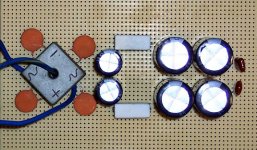
Sample:
This has 1 pair 4,700uF and 2 pair 10,000uF
Not shown: Notice the striped cable from the transfo is the 0v line, which also runs down the center of the power supply via a thick cable.
Not shown: Bleeder resistors under the first pair of 10,000uF
Not shown: Resistors shown are wrong--use Non-Inductive resistors or a length of interconnect cable instead.
Perhaps the prettiest power supply that I've made, and it took only 8 minutes.
EDIT: This is related to the carlosfm power supplies. See those threads here at DIYaudio.com for more information.
Attachments
- Home
- Amplifiers
- Chip Amps
- STK chips