I need to draw some diagrams to confirm, but this seems to indicate that asymmetrical horns have the wrong mouth shape.
Hmmm.
For instance, when you have a horn with a coverage angle of 90 degrees by 60 degrees, the 60 degree axis is narrower than the 90 degree axis. But if I'm reading Tom correctly, it should be the opposite. IE, the 60 degree axis would have to be larger than the 90 degree axis.
The only way to do that (which I can think of) would be to change the angle at some point along the horn.
Yup, that's pattern flip. Stay above it, or build square Synergies...
On second read of Nexo, I'm not sure if they are saying the shape
of a proper divergent mirror is a hyperbola, or an ellipse??? I did
not assume any geometry, but trial and errored 5 points till the
error was small, then connected the dots into a smooth curve.
Last edited:
I was actually playing around with ABEC3, to see if I could sim a paraline in it. I made the software work, but the results were awful without a horn to complete it, so I thought I would add a simple horn. I just saw Tom´s comments, and thought perhaps this drawing would help. And if I´m wrong, you guys will correct me.
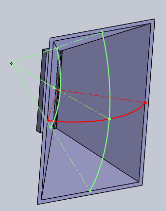
I aimed for a 60 degree vertical paraline with a standard rectangular exit.
The green sketch shows the apparent apex of the "squashed" dimension, while the red one shows the apex of the "diffraction slot".
If I wanted these to come together at the same point, I was forced to have the horizontal angle be 83.5 degrees.
If the height is 500mm, the width then needs to be 350mm, so height is about 1.5 times higher at these angles.
Attachments
Peaks of the temporary pvc roundovers are now 4.5 inches apart.
Should begin flipping at <1.5KHz and completely flipped by <750Hz.
We probably wasted a few dB of mids that went carpet and ceiling.
So, lets try a minimum of 8 inch sonotube next time we measure.
Peaks will then be 8.5inches apart, and flip wont start till <711Hz.
That should be OK with our crossover at 1KHz.
Zob's wish to synergy in some midrange drivers is going to need
an even taller horn mouth. Larger than the current vertical size
of the faceplate. 16 inch tube I think could work down to 400Hz.
Could be lazy, accept some flip, and throw a baffle step at it.
Last edited:
I need to draw some diagrams to confirm, but this seems to indicate that asymmetrical horns have the wrong mouth shape.
Hmmm.
For instance, when you have a horn with a coverage angle of 90 degrees by 60 degrees, the 60 degree axis is narrower than the 90 degree axis. But if I'm reading Tom correctly, it should be the opposite. IE, the 60 degree axis would have to be larger than the 90 degree axis.
The only way to do that (which I can think of) would be to change the angle at some point along the horn.
True, the dimension of a narrower coverage horn has to be larger than for a wider coverage horn of the same lower pattern control frequency. So for an asymmetric horn of the same depth, the lower pattern control frequencies will be different for horizontal and vertical, giving the "pattern flip".
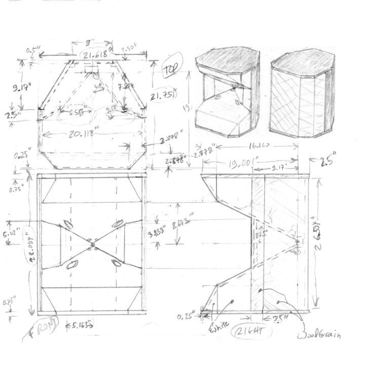
A way around that, I think (and plan to try when weather is amenable to woodworking outside!), is to make the depths of the horizontal and vertical parts different -- for instance, for a narrower vertical, have the top and bottom horn walls extend out further than the left and right walls. This would allow a box more narrow than high (usually more acceptable in a domestic room), though the overall depth will have to be that of the vertical horn.
Here's a sketch I put together, which I think might actually look decent, at least with a grill cloth. Or without, if not going for WAF --
Last edited:
Nice design Bill - I can't wait to see (and hear) it when you have a chance to build it, and I hope it meets your expectations!
After looking at cookiemonster77's design, my thoughts went off on a tangent. It's most likely wrong, but I wondered...
...how does the standard horn respond, compared to what a Paraline represents? Is the Paraline really just part of a horn?
So, has anyone compared the response of a Paraline with a 'cut off' conical horn?
Which then leads me to ask two things:
1. If the results are similar, the flare and mouth of the horn would definitely be necessary, correct?
2. If the results are different, what would it take to provide a response to that of an 'unfolded' horn?
I thought the answer to 2 was roundovers and distributed reflection time.
Of course I had to turn the slot on its side for roundovers not to mess with
the horizontal constant directivity. And in the end, it makes no difference
whatsoever.
On the other hand, neither this nor paraline measured bad as others say.
there may not be so much wrong in reality that needs elaborate fixing.
Bwaslo,
Very nice design there. It is a 3-way and what are the XO frequencies and how low were you going for bottom end bass extension? I always try to shoot for 100Hz in order to integrate with a sub. If one made this out of XPS foam sheathing, it would be very light weight.")
Very nice design there. It is a 3-way and what are the XO frequencies and how low were you going for bottom end bass extension? I always try to shoot for 100Hz in order to integrate with a sub. If one made this out of XPS foam sheathing, it would be very light weight.
Last edited:
Well, I had a go at simulating the Paraline (see post 862with BEM in Abec3. It´s probably strictly not a paraline, since I didn´t really think about dimensions.
It was really an experiment to see if the BEM solver could handle it, and if there are any learnings from it.
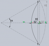
So, aiming for a 60 degree vertical angle, this is how to arrive at the curve. Draw the 60 degree arc, then make a parabolic arc with depth (D5) = D3/2-D4/2. This ensures that the total distance traveled is equal in all directions.
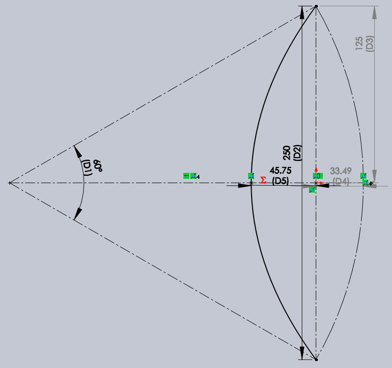
Note, the height (125mm) was randomly chosen - more on that later.
I thought it was a good idea to split the paths into segments - perhaps that was a bad idea, perhaps it works out well to reduce resonances in the material. ABEC doesn´t simulate that (i think), so it won´t matter here, but it could have other effects.
I won´t describe how all the layers look, I suppose it´s pretty standard, except I added 45 degree reflectors also inside the fold. (Easy to print, probably quite difficult to do with wood). The dividing layers are 2mm, while the other layers are 6.5mm, which I think ensures there is no additional compression at the entry of the paraline, disregarding the change in direction that is.
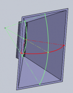
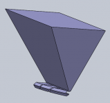
Horn added, like in the previous post.
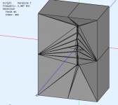
Getting the solid file into a mesh is quite easy, just export to STL. But for subdomain modelling, ABEC needs to know what´s the inside and what´s the outside. For that, I made a "negative", which basically shows the inside. That negative can be imported to ABEC, and normals reversed, so the mesh of the negative becomes the inside of the paraline and horn. From the image below, you can see the slanted reflectors inside the paraline.

In ABEC, the whole thing looks like this, after adding some simple walls to enclose the externals:
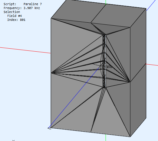
The model simulates everything inside the "negative" above as one subdomain, and then there is a boundary element across the horn mouth that lets radiation exit to subdomain 2 which is "everything else".
I set the mesh frequency to 10kHz, which translates into a rather fine grained mesh. Perhaps it´s too low, but with 10kHz it took about 1.5GB memory to solve, and memory requirements increase exponentially with mesh density. On my computer this took nearly 24 hours to solve for 100 frequencies between 100Hz and 20kHz.
The driving source for the analysis was a stock compression driver (i´m not sure which one even) that is included with ABEC. It has a one inch exit at least. If somebody has a known compression driver modelled in ABEC, let me know, and I can plug it in to see how the results are.
Anyway, here are the results:

Now, this is at 2m distance from the entry of the paraline driver. Pretty bad.
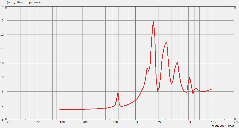
Impedance:
Ok, so how does this look "inside" the paraline. Since the paraline is folded, and I can only do "two dimensional" spectra, I chose the frequency of the second dip to examine, and only include the expansion layer after the entry.

One can clearly see two "modes" inside the paraline, caused by reflections I suppose. Why the SPL of the four center ducts are so much higher is beyond me, but it could be that the smaller path length to the bend cause the reflections to actually sum constructively there.
Anyhow, it does seem that the 250mm total length is way too much - set randomly as I mentioned.
It would be interesting to model one of the "successful" ones, or one with significantly smaller dimensions. Anybody care to suggest a length to try next?
I can also extract all kinds of charts from ABEC, but horn directivity etc is not that interesting with such a ragged response. But if there is interest, I could certainly post them.
It was really an experiment to see if the BEM solver could handle it, and if there are any learnings from it.
So, aiming for a 60 degree vertical angle, this is how to arrive at the curve. Draw the 60 degree arc, then make a parabolic arc with depth (D5) = D3/2-D4/2. This ensures that the total distance traveled is equal in all directions.
Note, the height (125mm) was randomly chosen - more on that later.
I thought it was a good idea to split the paths into segments - perhaps that was a bad idea, perhaps it works out well to reduce resonances in the material. ABEC doesn´t simulate that (i think), so it won´t matter here, but it could have other effects.
I won´t describe how all the layers look, I suppose it´s pretty standard, except I added 45 degree reflectors also inside the fold. (Easy to print, probably quite difficult to do with wood). The dividing layers are 2mm, while the other layers are 6.5mm, which I think ensures there is no additional compression at the entry of the paraline, disregarding the change in direction that is.
Horn added, like in the previous post.
Getting the solid file into a mesh is quite easy, just export to STL. But for subdomain modelling, ABEC needs to know what´s the inside and what´s the outside. For that, I made a "negative", which basically shows the inside. That negative can be imported to ABEC, and normals reversed, so the mesh of the negative becomes the inside of the paraline and horn. From the image below, you can see the slanted reflectors inside the paraline.
In ABEC, the whole thing looks like this, after adding some simple walls to enclose the externals:
The model simulates everything inside the "negative" above as one subdomain, and then there is a boundary element across the horn mouth that lets radiation exit to subdomain 2 which is "everything else".
I set the mesh frequency to 10kHz, which translates into a rather fine grained mesh. Perhaps it´s too low, but with 10kHz it took about 1.5GB memory to solve, and memory requirements increase exponentially with mesh density. On my computer this took nearly 24 hours to solve for 100 frequencies between 100Hz and 20kHz.
The driving source for the analysis was a stock compression driver (i´m not sure which one even) that is included with ABEC. It has a one inch exit at least. If somebody has a known compression driver modelled in ABEC, let me know, and I can plug it in to see how the results are.
Anyway, here are the results:
Now, this is at 2m distance from the entry of the paraline driver. Pretty bad.
Impedance:
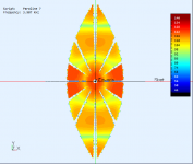
Ok, so how does this look "inside" the paraline. Since the paraline is folded, and I can only do "two dimensional" spectra, I chose the frequency of the second dip to examine, and only include the expansion layer after the entry.
One can clearly see two "modes" inside the paraline, caused by reflections I suppose. Why the SPL of the four center ducts are so much higher is beyond me, but it could be that the smaller path length to the bend cause the reflections to actually sum constructively there.
Anyhow, it does seem that the 250mm total length is way too much - set randomly as I mentioned.
It would be interesting to model one of the "successful" ones, or one with significantly smaller dimensions. Anybody care to suggest a length to try next?
I can also extract all kinds of charts from ABEC, but horn directivity etc is not that interesting with such a ragged response. But if there is interest, I could certainly post them.
Attachments
-
 60 deg1.png49.5 KB · Views: 1,504
 -
 negative paraline and horn.png26.6 KB · Views: 1,496
 -
 before meshing.png40 KB · Views: 1,488
 -
![2014-12-04 22_27_39-VacsViewer - (new) - [Sound pressure].png](/community/data/attachments/421/421896-f25ccce36aa7e10ace2c92c276a6f5a7.jpg) 2014-12-04 22_27_39-VacsViewer - (new) - [Sound pressure].png34.9 KB · Views: 2,629
2014-12-04 22_27_39-VacsViewer - (new) - [Sound pressure].png34.9 KB · Views: 2,629 -
![2014-12-04 22_33_01-VacsViewer - (new) - [LE_Spectrum #7].png](/community/data/attachments/421/421906-199474925f894e02e77789ae8390808e.jpg) 2014-12-04 22_33_01-VacsViewer - (new) - [LE_Spectrum #7].png34.8 KB · Views: 1,456
2014-12-04 22_33_01-VacsViewer - (new) - [LE_Spectrum #7].png34.8 KB · Views: 1,456 -
 2014-12-04 22_35_33-ABEC3 - Paraline 7.png35.8 KB · Views: 1,465
Cookiemonster,
You are the man! Very nice simulation.
This is the first 3d BEM (FEA) I have seen of a Paraline. Great work!
I have to step up to ABEC3 one of these days. I have SW too.
Here is a 1d Akabak model of my Paraline (a little different but same concept of flat folded channels) from Post 759 or so. I got some really ratty looking response curves too:
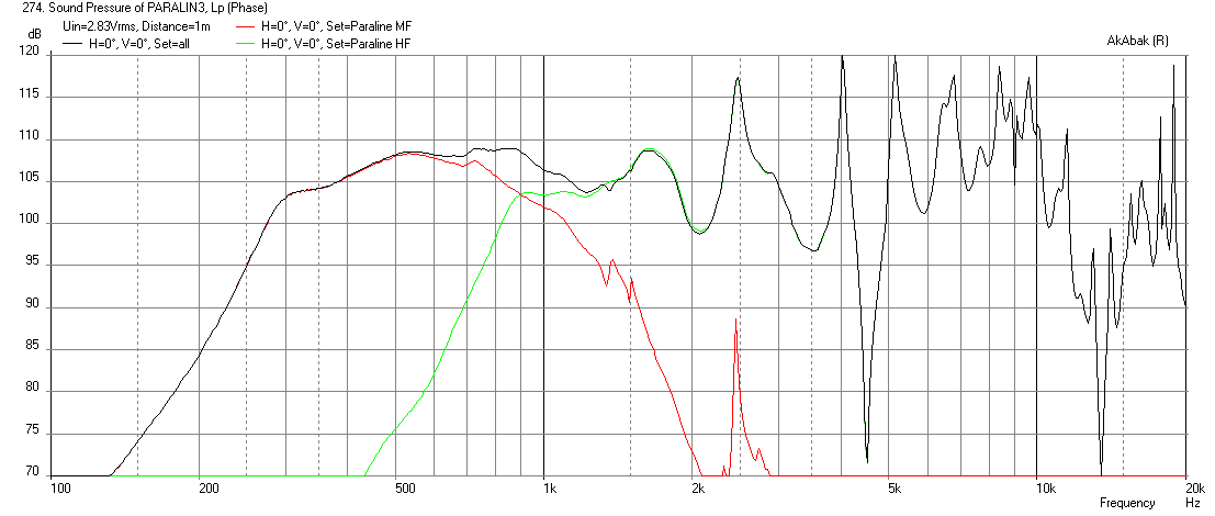
Looks kind of similar to your 24hr sim:
You are the man! Very nice simulation.
This is the first 3d BEM (FEA) I have seen of a Paraline. Great work!
I have to step up to ABEC3 one of these days. I have SW too.
Here is a 1d Akabak model of my Paraline (a little different but same concept of flat folded channels) from Post 759 or so. I got some really ratty looking response curves too:
Looks kind of similar to your 24hr sim:
Last edited:
Bwaslo,
Very nice design there. It is a 3-way and what are the XO frequencies and how low were you going for bottom end bass extension? I always try to shoot for 100Hz in order to integrate with a sub. If one made this out of XPS foam sheathing, it would be very light weight.
Hi xrk971,
The plan (at present) is to use a DE5 as tweeter (for pattern coverage to a higher HF frequency), cross to mid at around 2500Hz. Mid is probably 4x Faital 3FE22, cross to woofers at about 500Hz or higher. Woofers a pair of 10FE200-4. Looking for <85Hz if sealed, or 50ish Hz if I port (I have to rerun models to see if those are right... this has been shelved since about April).
At least that's the plan, likely to change as always!
Check out some of my projects. I once used the Faital 3FE20, but I've found that the Dayton ND91 works better.
I've also used the B&C DE10 for a Synergy project.
My latest project uses four of the ND91s and a Vifa XT25. If cost was no object, I'm not sure if the XT25 would be my choice. But at a cost of $20 each, it's tough to beat.

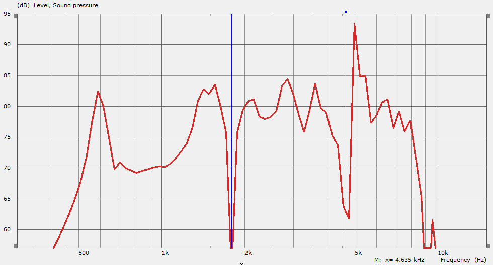
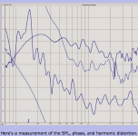
Here's a measurement of the SPL, phase, and harmonic distortion. This is at 45 degrees off axis. (Which is the listening axis.) The measurement is kinda rough bcuz I did it in my living room. But you can see that the $19 Vifa keeps distortion 30+ dB below the fundamental. Works quite nicely on a waveguide.
Cookiemonster,
You are the man! Very nice simulation.
This is the first 3d BEM (FEA) I have seen of a Paraline. Great work!
I have to step up to ABEC3 one of these days. I have SW too.
Here is a 1d Akabak model of my Paraline (a little different but same concept of flat folded channels) from Post 759 or so. I got some really ratty looking response curves too:
Looks kind of similar to your 24hr sim:
Agreed, thanks cookiemonster77 for your exhaustive experiment!
Looking at the '2d spectra' image, it seems to suggest that something is possibly happening cancellation-wise with relation to the vertical and horizontal dimensions. That null at 1.8kHz...could that be such a thing, and how does that (the wavelength of 1.8kHz) relate to the internal dimensions of the paraline?
It appears to repeat higher up too...
Hi xrk971,
The plan (at present) is to use a DE5 as tweeter (for pattern coverage to a higher HF frequency), cross to mid at around 2500Hz. Mid is probably 4x Faital 3FE22, cross to woofers at about 500Hz or higher. Woofers a pair of 10FE200-4. Looking for <85Hz if sealed, or 50ish Hz if I port (I have to rerun models to see if those are right... this has been shelved since about April).
At least that's the plan, likely to change as always!
That's a nice choice!
X,3FE22's are excellent horn drivers - they go up to 18kHz in my tractrix. I get plenty of SPL and very low cone movement I wonder if you really need 4. I am able to get 110dB at 2.8v and 1m with one driver and cone moves less than 100 microns.
I can sing louder than 115 dB at one meter, wonder how many microns my vocal chords move :^)?
Art
Last edited:
"Patrick",Here's a measurement of the SPL, phase, and harmonic distortion... But you can see that the $19 Vifa keeps distortion 30+ dB below the fundamental.
I can see the distortion level rising 20+ dB above the fundamental frequencies below around 160 Hz, well over 100% distortion.
What was the approximate SPL of that measurement demonstrating distortion in excess of 100%?
Art
Attachments
Last edited:
X,
I can sing louder than 115 dB at one meter, wonder how many microns my vocal chords move :^)?
Art
Lol.
But can you sing notes at 115dB with less than -55dB THD? I would imagine vocal chords are moving quite a bit (3mm?) hence the cause of hoarseness if done for an extended time.
"Patrick",
I can see the distortion level rising 20+ dB above the fundamental frequencies below around 160 Hz, well over 100% distortion.
What was the approximate SPL of that measurement demonstrating distortion in excess of 100%?
Art
I measured in my living room. The gate is set long enough
to get a general idea of what the response is. But the lower you go, the less accurate, due to reflections.
I measured at -10dB from the maximum output on my amp. Its about 50 watts, so thats probably around 95dB
Last edited:
I measured in my living room.
I measured at -10dB from the maximum output on my amp. Its about 50 watts, so thats probably around 95dB
In room distortion level rising 20+ dB above the fundamental frequencies, well over 100% distortion, around 5 watts producing only 95 dB is, IMHO, effing pathetic.
I can sing 20 dB (four times) louder than that. A speaker that can't even reproduce the level of a single human voice without gross distortion should IMHO be relegated to background music use in a portable picnic pack-away stereo
. But of course, as long as you like the way it sounds, MHO makes no difference .By the way, the maximum output of an amplifier occurs when it is driven in to hard clipping, causing harmonic distortion. Are you sure the amp was not clipping?
Art
Last edited:
- Home
- Loudspeakers
- Multi-Way
- Square Pegs