It exits from the "mouth", which is the rectangular boundary around the whole thing.
http://www.danleysoundlabs.com/products/loud-speakers/synergy-horn/
http://www.danleysoundlabs.com/products/loud-speakers/synergy-horn/
OK. I suppose the lens it fed would be quite large.

The lens is only there to reflect the energy 90 degrees
Here's the thing:
If you use a driver that's already omni, then you don't need the lens.
For instance, if you want to play to 20khz, then you would need a driver that's 0.675" in diameter. Because the high frequency driver is bigger than that, we need a lens to reflect the energy that's beaming.
Once you understand that, you'll realize you can 'tweak' the radiator sizes so that only one lens is needed.
Here's an example:
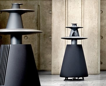
Let's say I want to do a Synergy two way with a B&O lens.
Let's say that I want my crossover to be at 1350hz.
In that scenario, I can use a woofer that's as large as 10" and I won't need a lens. This is because a 10" radiator won't start to "beam" until the wavelengths are smaller than the radiator. In this scenario, that means that the 10" woofer can be pointed straight up, and it will still radiate in all directions.
An externally hosted image should be here but it was not working when we last tested it.
Linkwitz uses this to his advantage in the Pluto and the LX Mini.
If you look at an overhead view of the Pluto, LX Mini, and *all* of the B&O speakers, you'll see they all do the same thing. The tweeter is at the center, with the woofers stacked below it.
On the horizontal axis, this keeps all the wavelengths in phase.
Now, at this point, you might be wondering why Linkwitz and B&O are using 5" woofers instead of 10" woofers. That's because of the rolloff of the woofers. IE, a 10" woofer may be omni up to 1350hz, but if we crossover at 1350hz then we also have to be sure the radiation is correct *above* the crossover point.
Due to that, it makes sense to reduce the size of the woofer.
Another way of reducing the radiator size is to use a coupling chamber. In the Danley Synergy horns you have four 5" woofers radiating from holes with a surface area of about 1" each. (There are 8 holes total.)
So Danley is "cramming" the equivalent of a 10" woofer through a hole that's about 2" in diameter, spread out across eight holes.

You can do the same thing with a Beolab, in fact I've done it personally.
I hope that made sense, this post was extra-confusing

Last edited:
If only the sound would behave like a ray!! Trouble is that it doesn't, its a wave. This is the same classic problem that people use with horns - they assume the sound waves travel like they want them to. Problem is that sound travels like it wants to, not like how you tell it that it should.
If only the sound would behave like a ray!! Trouble is that it doesn't, its a wave. This is the same classic problem that people use with horns - they assume the sound waves travel like they want them to. Problem is that sound travels like it wants to, not like how you tell it that it should.
I'm glad someone agrees with me...
http://www.diyaudio.com/forums/multi-way/217298-square-pegs-78.html#post4094395
If only the sound would behave like a ray!! Trouble is that it doesn't, its a wave. This is the same classic problem that people use with horns - they assume the sound waves travel like they want them to. Problem is that sound travels like it wants to, not like how you tell it that it should.
I never claimed it did.

In a SAW lens, higher order modes are scattered in the room.
In a Paraline lens, higher order modes are scattered inside of the lens.
That's one of the reasons I keep making the case for SAW lenses, and for *very small* Paralines.
For instance, even a 4" tall Paraline "loads" down to approximately 1688hz. So these big Paralines are going to be plagued with HOMs across their entire bandwidth.
Basically, I believe the following to be true:
1) both devices will suffer from HOMs
2) the larger the device is, the lower in frequency the HOMs will be
3) the HOMs in the SAW lens are able to "escape" the lens because the soundwave radiates in three dimensions. Basically when there's HOMs they'll be less offensive, as they wont be "trapped" in the lens, like in a Paraline
Thanks Patrick. Your description makes a lot of sense, and I had that 'a-ha' moment with the design of the Linkwitz speakers. Thanks!
I think what you did with the Beolab is similar to what I had in mind. You haven't mentioned it so I assume not, but does directivity become a problem for the woofer as the frequency rises? I suppose that depends on the driver, and how 'omni' it is...
Do you have any videos/recordings online of your Beolab experiment?
Last edited:
Thanks Patrick. Your description makes a lot of sense, and I had that 'a-ha' moment with the design of the Linkwitz speakers. Thanks!
I think what you did with the Beolab is similar to what I had in mind. You haven't mentioned it so I assume not, but does directivity become a problem for the woofer as the frequency rises? I suppose that depends on the driver, and how 'omni' it is...
Do you have any videos/recordings online of your Beolab experiment?
Directivity is basically dictated by the dimensions of the radiator.
If you look at the spec sheets of a hundred 5" woofers, you'll notice that they all start to beam about the same point:
They beam when the wavelength is smaller than the radiator.
There's some "tricks" you can do, of course.
Full range drivers are designed so that the radiator virtuall shrinks at high frequency, basically the center of the cone is decoupled from the rest. Take a look at an FF85WK and you'll see a thin band of polymer that decouples the center from the rest of the cone.
And coupling chambers can make a large cone behave like a smaller cone.
But besides that, it's basically boils down to the size of the radiator.
I'll post some videos the B&O thing later...
If only the sound would behave like a ray!! Trouble is that it doesn't, its a wave. This is the same classic problem that people use with horns - they assume the sound waves travel like they want them to. Problem is that sound travels like it wants to, not like how you tell it that it should.
I agree too Earl! I suppose that knowing how sound waves work allows us to be creative within our limitations. I have lots of them, so I try to remain creative
If only the sound would behave like a ray!! Trouble is that it doesn't, its a wave. This is the same classic problem that people use with horns - they assume the sound waves travel like they want them to. Problem is that sound travels like it wants to, not like how you tell it that it should.
Quantum mechanics would be an extremely accurate but fairly
inefficient way to design an integrated circuit, dump truck, or
loudspeaker enclosure. Obviously we are not going to do that,
because scale matters.
Computational fluid dynamics are still a little out of reach for
the DIY crowd. But that's the least cheatie way currently to
simulate an acoustic system without some more serious form
of cheat (like raytraces, or compartmentalized simulations) to
make things even more manageable.
For spaces wider than 1/4 wavelength, optical raytraces are a
useful and relevant way to visualize the aggregate behavior of
multiple waves and high order modes. For smaller spaces, optics
are an utterly useless way to describe what happens. Acoustic
waveguides happen to fall right on the grey edge of that rule.
The relevance of optics to acoustics will vary with frequency.
Abusing a simplified rule in an inappropriate situation or at an
inappropriate scale will lead to inaccurate conclusions. Quite
a few only ever seem to reach for one hammer in their toolbox,
or never reach for that hammer when it could really help.
Last edited:
Hi
Hi Guys
I had suggested that the Paraline was something the DIY’r might want to skip over as there are a number of things about it that are not obvious and a highly asymmetric dispersion pattern is not normally required in the home.
A few pitfalls for example, if one makes a Paraline out of stacked plates, the tiny air gap left between plates is a situation that can act as a low pass filter, can cause ripples in the response, same for making one out of wood, if the pores of the wood are left open, these can attenuate the hf response as well.
A similar thing exists at the bends, sound will happily flow around a corner as one can see from the inside of a phase plug BUT when the inner and outer path around that bend reach about ½ wavelength difference, there is cancellation and most of what I have seen from the DIY area are dimensions which would not allow high frequencies to propagate without being affected.
Also, the shape of the correction slot or “eye” is not a simple curve, it’s more like a parabola or hyperbolic curve who’s shape is dictated by the need to have all the paths the same length from the source to exit wavefront shape. While the flat front “line” is the simplest one to make, it is the least desirable for the same reason a ribbon the same length would be.
One can generate higher order modes or internal reflections should one place a discontinuity in the paths but on the radial expansion side, in one plane the dimensions are too small acoustically to support a reflection and radially there are no walls to cause a reflection. As long as the eye is the right shape and the same dimensions as the path leading up to it, there is nothing to produce a reflection, just as it is in a phase plug where the sound has to bend / flow like a fluid pressure.
If you want to make one that works properly, pay attention to the thickness dimension of the passageway before during and after the bend and mill it / print it out of plastic or metal ie: that has no porosity and is solid and dead. Think about how large a 20Khz wavelength is (if you need 20K) Fwiw, I poured polyurethane through the first wooden ones I made to seal them off and fill any gaps.
What can be a large factor is that one terminates a Paraline with a final horn segment which ideally has the shape needed to avoid pattern flip and terminates the horn section in the Paraline so that it isn’t too much of a discontinuity itself but sometimes one has no choice given the second sections arrangement. For example the sbh-10 has 8 drivers and has a very narrow vertical pattern but the real gain from it is that unlike a row of direct radiators, it radiates far less energy outside the desired pattern and has the output of 8 small compression drivers.
As pointed out in the write up Pat Brown did about minimum measurement distance, a source that has dimensions, has a minimum measurement distance before the radiation behavior has stopped changing vs distance. One finds that if you measure a line segment the same size, even if it’s a perfect transducer, that radiation shape causes a “grassy” measurement and to measure it accurately, one must follow the criteria Pat wrote about.
Also too, the only reason to use a Paraline is to make a CD horn with a very asymmetric pattern. Beyond about a 1.5:1 aspect ratio, a simple “pyramid” shape horn exhibits pattern flip which can affect the audience coverage.
The mouth shape and wall angles needed to avoid pattern flip with highly asymmetric horn requires it be driven by an astigmatic point source horn and that is where the Paraline comes into it, it bypasses the need for a VERY deep throat section needed if one’s vertical angle is very small compared to the horizontal angle.
Patrick, I know you’re a “builder” and make saw dust and I know you have made a few Synergy /Unity style horns. If you still have one, take the measurements from what you built and then work out a crossover that doesn’t have the normal N-order * 90 degrees crossover phase shift. Part of “the sound” comes about when you have is acting like a single driver, not what one has with an “all pass” crossover phase shift.
Best,
Tom
What of those crossovers that roll the bass then subtract to drive the mid.
roll the mid then subtract to drive the treble? Cross a little higher, and with
overlapping capabilities that the higher driver can survive the abuse. Is this
a rational way to a unity output that is all in phase?
Or maybe roll the trebles and subtract from pure flat to drive the lower?
Seems to be whats going on over here:
Subtractive Crossover Networks
Though Elliot warns this makes a bump in the lowpass that
doesn't work unless it acoustically sums with highs, including
the directivity. Look to his Figure #9
To quote ESP, "The first - and possibly the most important -
thing that must be understood is that electrical and acoustical
summing are not the same thing."
My thoughts are : Except maybe in this one special case...
And : Perhaps should we delay and roll before subtracting???
Or does that mean the mids have to play all the highs louder
than the compression driver to drown out the summing error?
I got it backwards... Subtract then delay mids, no problem...
Except now the mids are playing higher than usual. And maybe
not far enough back in the throat unless planned in advance.
Last edited:
What of those crossovers that roll the bass then subtract to drive the mid.
roll the mid then subtract to drive the treble? Cross a little higher, and with
overlapping capabilities that the higher driver can survive the abuse. Is this
a rational way to a unity output that is all in phase?
Or maybe roll the trebles and subtract from pure flat to drive the lower?
Seems to be whats going on over here:
Subtractive Crossover Networks
Though Elliot warns this makes a bump in the lowpass that
doesn't work unless it acoustically sums with highs, including
the directivity. Look to his Figure #9
To quote ESP, "The first - and possibly the most important -
thing that must be understood is that electrical and acoustical
summing are not the same thing."
My thoughts are : Except maybe in this one special case...
And : Perhaps should we delay and roll before subtracting???
Or does that mean the mids have to play all the highs louder
than the compression driver to drown out the summing error?
I got it backwards... Subtract then delay mids, no problem...
Except now the mids are playing higher than usual. And maybe
not far enough back in the throat unless planned in advance.
Hi Ken
Do you have a crossover modeling program like lspcad?
Since no horn driver and CD horn will have “flat response”, part of the “crossover” task is also equalization and both of these impart a commensurate phase shift as well. That is what modifies the drivers “not flat” raw response.
In a simple 2way crossover, when you look at the overall phase, you see an “all pass” phase response and flat amplitude. Your right about delay. If you said ok, to fix the phase, I am going to delay the hf by an amount approximately what the group delay curve suggests and inverts it, then you’re getting closer. The problem is what one needs is not a “named filter” but one that is the “right shape” for the magnitude and phase of the raw response for each range and that given the delay imposed by the front to back / depth separation between the upper and lower range. If you are doing this electronically, one has the ability to add delay if needed. Where each frequency range combines with it’s neighbor, the sources are all less than ¼ wavelength apart in the horn and in a range where they overlap, they even feel some “mutual coupling” effect (like close coupled subwoofers do). In a perfect crossover world, one ends with the phase shift related to the low and high frequency drivers but no crossover.
Unfortunately, I would guess it’s close to impossible to arrive at this using real drivers responses without a computer program that iterates and that one can assign a phase target as well as amplitude.
Best,
Tom
I think Ken was just asking about whether active subtractive crossovers specifically might work out there. I think potentially, if you also have active circuits EQing the drivers first, but there may be a problem with keeping the acoustic rolloff shallow enough for the LF drivers, and it's only making a difficult task even more difficult. Ditching the whole subtractive concept and bringing in the brute force of FIR DSP would probably make more sense.
If you play around with 2nd order target slopes enough with your eye on phase, and your driver arrangements / delays are accommodating, you can get an approximation of "transient perfect" behavior. I think that's what Tom does in those horns that make almost-square waves, but I don't know?
If you play around with 2nd order target slopes enough with your eye on phase, and your driver arrangements / delays are accommodating, you can get an approximation of "transient perfect" behavior. I think that's what Tom does in those horns that make almost-square waves, but I don't know?
Last edited:
If only the sound would behave like a ray!! Trouble is that it doesn't, its a wave. This is the same classic problem that people use with horns - they assume the sound waves travel like they want them to. Problem is that sound travels like it wants to, not like how you tell it that it should.
That's not entirely true. If the wavelength is significantly small in relation to the acoustical image size of the reflector it will behave much like a ray. If this was not true then Huygen’s wave front reconstruction principle would be incorrect. I have recreated similar (if not near identical) results as Bruce Edgar has shown in his Show Horn and Monolith articles. When the distance between folds are 1/2 wave length apart you will get a cancelation at that frequency. The horn will behave much like a muffler at that frequency. However, if you treat the corners with ray tracing in mind the response holes fill in nicely. I go one step further and chamfer the inside bends so the horn expansion is not constricted and disrupted.
http://volvotreter.de/downloads/Edgar-Show-Horn.pdf
http://volvotreter.de/downloads/Edgar-Monolith-Horn.pdf
That's not entirely true.
Nothing is ever entirely true.
Assuming "rays" of sound is a dangerous way to approach acoustics problems in speaker design because speakers are always right in the middle of the wavelength transition region. In an optical lens this is never the case, which is why rays work just fine there.
The actual responses for the BeoLab thingy are nothing like what one might expect from ray tracing.
Correct, if we assume that all sound behaves like rays we would be wrong. It is frequency dependent based on the physical dimensions of the horn folding. When the wave lengths are significantly larger than the acoustic image size of the reflector, the sound transitions into behaving more like laminar flow. The BeoLab does have issues. It does not provide a solution for the entire bandwidth which the transducer is being used.
- Home
- Loudspeakers
- Multi-Way
- Square Pegs