You are totally missing the point that there are 3 dimensions.
Only one of them is thin enough to behave mostly as-if a fluid.
Other two are large enough that optical rules are still relevant.
But at the point where the flow goes through the narrow slot, it is small in both the axial (propagation axis) and in the slot width axis, leaving only the slot length axis large enough to sustain transmission of optical-like properties, which is not the direction that you are ray tracing. As the the other two dimensions are below the wavelengths of interest, once the flow has made its way through the hairpin turn, it basically starts all over as a new wave propagating out. In this case, the new wave starts along the slit axis and expands out. There is no "focusing" going on internally - it is all a matter of pathlengths and propagation distances. Again, when it gets to the final exit terminus slit, with dimensions smaller than the wavelengths of interest, it resets itself again as a new oscillatory pressure sound source. Essentially the paraline is like a large phase plug inside a compression driver (which follows the same principles and has no focusing or other optical like effects).
I see that we disagree on this, and that is fine. Maybe some measurements of sound pressure spectrum along the slit axis may show how uniform the flow is.
I know that it's likely to be impossible, but would there be a way to measure the physical properties of air in these devices?
I keep getting conflicted messages in my head about this subject. It all seems to make sense, but the conclusions are dependent on a particular approach.
The 'unknowns' that I have when trying to visualise either a Paraline or a Smithagrain is what air actually does within the confines of the small spaces. How 'springy' is it (how much actual pressure to compress the molecules)? As this is, like horns are, an acoustic coupler, what do(es) the driver(s) see in terms of compression ratios and back pressure?
Is the exit pressure of either device lower at the exit compared to where the drivers fire? Sorry for the novice question there, but it would seem necessary in order for it to mimic a horn. (Possibly a throw-away comment, my apologies if it's not really relevant)
I know the issue of reflectors (at least for within the Paraline) have been mentioned before in this thread, and it would seem to make sense to use them rather than molcules getting stuck in a right-angled corner, but how important are they, internally?
On a slightly different approach, I'm still intrigued by the idea of stacking paralines...with multiple conical profiles, one could mimic an exponential flare. But, how does one couple one Paraline to another? Does the overall compression ratio go up so much that it's not advisable unless you're using compression drivers (e.g. $800 JBL 2447s or something)?
I apologise for thinking aloud, but this thread is really very interesting. Maybe it's on the pursuit to the phrase 'there's no magic bullet', but maybe it's also close to a design that hasn't quite been discovered yet that paves the way for some very cool space-saving approaches. I can handle a horn mouth of 4 feet (vertically and horizontally), but the length of said horn unfolded isn't practical.
Last edited:
AkAbak can model a CD's internal geometry with good accuracy of the correct physical measurements of dimensions of the flow passages and phase plug are known along with TS params. AkAbak can model a macro horn accurately. This is somewhere in between and I have to imagine that it can model it accurately as well. If it does then the air is behaving like a normal horn that can be represented as a 1d lumped element model. If that is the case then all the concepts of flow impedance, compression ratio, etc all apply.
Ah, that's good! I've never played with Akabak, but it's definitely a successful design system! Does it have any animated simulation features?
This discussion reminds me of this:
https://www.youtube.com/watch?v=HpovwbPGEoo
")
This discussion reminds me of this:
https://www.youtube.com/watch?v=HpovwbPGEoo
I've done my best, I'll let someone else take a try at explaining it.
Here's all I need to know:
1) Nate Hansen wrote the following:
"Someone mentioned my Paralines a few days ago, and put up a link. The measurement shown, I'm fairly sure, is 1/6 octave smoothed. The response with higher resolution is absolutely awful.
I used them for about a year and a half, but really they were only good for background music.....if that even."
2) Art was the first to clone Paralines, and Art has mentioned numerous times that he prefers "conventional" Synergy horns for hifi use
3) I built a whole bunch of Paralines, and I gave up.
I'm not saying that Paralines don't work. They DO work, but the diffraction artifacts are noticeable.
If I needed narrow vertical directivity and wide horizontal directivity I would use a Sausalito Audio Works lens or a ribbon.
Thanks Patrick.
Your last comment here sparked a thought - could this cone folding method be used for more conventional dispersion patterns...I don't know, say 30 degrees vertically and 90 horizontally?
Or is that just a wasted exercise?
You can get a vertical pattern of anything from zero degrees to 180 degrees using a Paraline, and you can even get negative degrees.
You can do the same with the L'Acoustic Docsis waveguide.
The Docsis predates the Paraline, but it's basically the same thing.
The advantage of the Docsis is that the bends are ninety degrees.
The disadvantage is that it's quite complex to build. (A 3D printer would be very helpful here.)
An externally hosted image should be here but it was not working when we last tested it.
With either device you can get 30 by 90. To get 30 by 90 you would have a 30 degree Paraline feeding a 90 degree waveguide. The VTC boxes are 10 x 90 IIRC. Note that you'll get horizontal diffraction at the Paraline exit, because you have an abrupt change in the horizontal directivity at the exit. It's likely that the smooth sound of the Synergy horns is due to the fact there's diffraction at the compression driver exit and the mouth exit, but the change in angle is gentle so diffraction is minimized.
If you listen to the videos of the Genesis horns, many of them sound quite good, and it just occurred to me that the Layered Combiner doesn't have the 180 degree bends of the Paraline.
So that may be why.

I'd always wondered why Danley used the Layered Combiner in the Genesis horns, when an array of Paralines could achieve the same result. But that might explain it. (Pure conjecture on my part.)
Again, I think the Paraline is neat, but the diffraction is a problem. If the frequency range was lowered the diffraction would likely be less audible, as diffraction seems to be more offensive at high frequencies than low.
And there's nothing stopping someone from making a three meter tall Paraline.
Last edited:
Here's all I need to know:
1) Nate Hansen wrote the following:
"Someone mentioned my Paralines a few days ago, and put up a link. The measurement shown, I'm fairly sure, is 1/6 octave smoothed. The response with higher resolution is absolutely awful.
I used them for about a year and a half, but really they were only good for background music.....if that even."
2) Art was the first to clone Paralines, and Art has mentioned numerous times that he prefers "conventional" Synergy horns for hifi use
3) I built a whole bunch of Paralines, and I gave up.
I'm not saying that Paralines don't work. They DO work, but the diffraction artifacts are noticeable.
If I needed narrow vertical directivity and wide horizontal directivity I would use a Sausalito Audio Works lens or a ribbon.
Although I don't technically have a paraline design, I do have the sharp 180 deg folds and I agree that the diffraction artifacts combined with what the folds do to the frequency response as shown in both the sims and measurements inidcate that its not worth pursuing further if high fidelity domestic audio is what you are after.
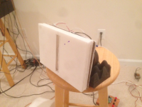
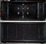
Here is a photo of the speaker during the test:

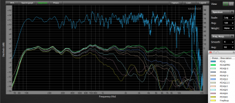
Here is a measurement of the response showing the LF drivers (full range) and the HF piezo tweeter (3.3uF series cap HPF):
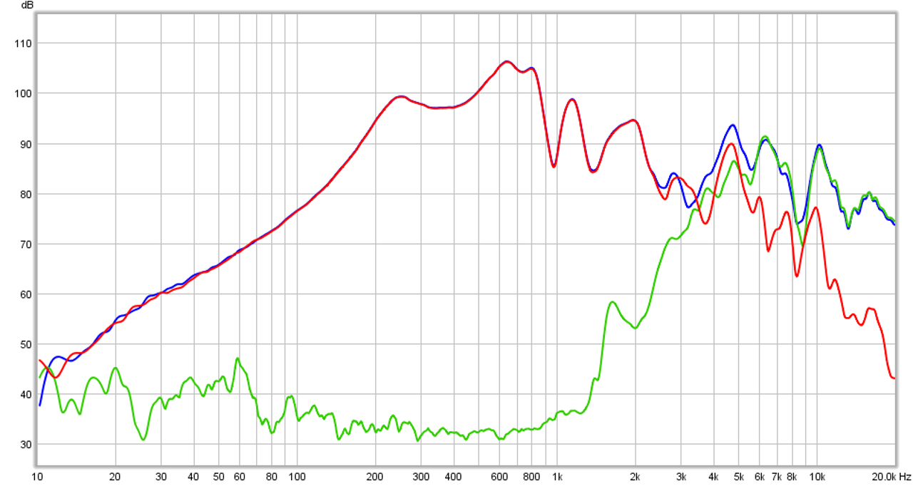
Granted, if I had a higher sensitivity CD for the HF's the amplitude levels would be more balanced, but that would not change the "pine trees in forest" frequency response profile I am getting, which I believe, is not totally inconsistent with some of the other measurements that are out there. On the plus side, it looks like the simple mid freq injection ports for a pancake synergy are working well and the cheap sealed back driver is getting down to 200Hz or so.
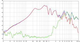
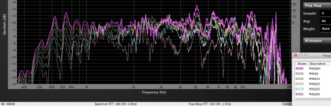
Here is a measurement of the amplitude variation along the slot axis at 2cm away (0, 1.0, 2.0, 2.5, 3.0, 3.5, 4.0, 5.0, 6.0 in locations, with 0in and 6in at the very edge of the slot) - I don't see any "beaming" or light ray like "focusing" going on here:

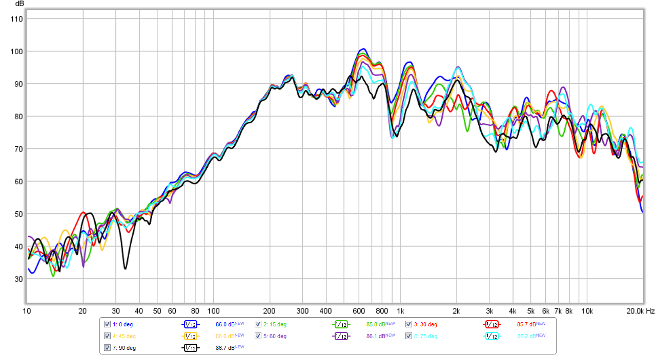
And here is a measurement of the polar response at a distance of 12in away:
Attachments
Last edited:
Thanks for your documentation X! The results show us that this folded technology is pretty consistent in its performance.
Out of interest, what is the expected compression ratio of the horn?
What is your opinion of its sound?
The midrange output is quite nice (I'm thinking 200-1000Hz), so do you think it would be of use as a replacement to a large midrange horn?
From your experiences, do you think there would be an approach that could be used to create a smoother frequency response in a similar design? I'm not necessarily thinking that either the Paraline or Smithagrain are modified ad nauseum, but maybe they inspire another method...
Last edited:
UnaHMM,
You are welcome! I hope to provide some insight into a unique and very easy to make flat horn.
The compression ratio in the driver chamber is actually quite high with cone area of circa 10 in2 and the injection port area of about 1in2 - so circa 10:1 compression ratio, The flat folded horn itself goes from 1.2 in to 6 in expansion or 5:1 ratio.
The bandpass nature of the mid port really restricts how much HF can get out from the mid driver. But what does get out has a very uniform dispersion as you can see from the polar plots. If I did this properly with a good CD, active miniDSP XO and bi-amps, I would imagine it could sound pretty decent. Given that I cheaped it out with full range on the mids and a simple high pass cap on a piezo tweeter that is underpowered, the sound was passable as background music. But I should reserve judgement on sound quality when properly built out of wood and driven with correct XO and drivers.
The SPL coming out is lower in sensitivity than the driver is capable of - I think if an additional front horn is added you recover some losses. Although some of this may be losses in foam core. To be fair, I should make one in wood or plastic before commenting. it does seem to allow a very compact integration between HF and MF drivers though and the MF is smooth and extends the full height of the 6in slot - making for a nice entry into a wide dispersion horn with narrow vertical directivity.
Maybe make smoother rounded 180 deg hairpin turns and make it using 3d printing. That would enable exact paths and curves easily.
You are welcome! I hope to provide some insight into a unique and very easy to make flat horn.
Out of interest, what is the expected compression ratio of the horn?
The compression ratio in the driver chamber is actually quite high with cone area of circa 10 in2 and the injection port area of about 1in2 - so circa 10:1 compression ratio, The flat folded horn itself goes from 1.2 in to 6 in expansion or 5:1 ratio.
What is your opinion of its sound?
The bandpass nature of the mid port really restricts how much HF can get out from the mid driver. But what does get out has a very uniform dispersion as you can see from the polar plots. If I did this properly with a good CD, active miniDSP XO and bi-amps, I would imagine it could sound pretty decent. Given that I cheaped it out with full range on the mids and a simple high pass cap on a piezo tweeter that is underpowered, the sound was passable as background music. But I should reserve judgement on sound quality when properly built out of wood and driven with correct XO and drivers.
The midrange output is quite nice (I'm thinking 200-1000Hz), so do you think it would be of use as a replacement to a large midrange horn?
The SPL coming out is lower in sensitivity than the driver is capable of - I think if an additional front horn is added you recover some losses. Although some of this may be losses in foam core. To be fair, I should make one in wood or plastic before commenting. it does seem to allow a very compact integration between HF and MF drivers though and the MF is smooth and extends the full height of the 6in slot - making for a nice entry into a wide dispersion horn with narrow vertical directivity.
From your experiences, do you think there would be an approach that could be used to create a smoother frequency response in a similar design?
Maybe make smoother rounded 180 deg hairpin turns and make it using 3d printing. That would enable exact paths and curves easily.
Maybe make smoother rounded 180 deg hairpin turns and make it using 3d printing. That would enable exact paths and curves easily.
That would make sense. To me, with an application such as this, the goal is more to 'steer' the air around the device, rather than bouncing it around in an abrupt manner.
Some of the reflectors that I've seen being talked about on this forum, especially with horns gives rise to a specific design. Thinking about it in my head, the cross-section of the devices we're working on in this thread would be...wait for it...elliptical in shape! Obviously it would be squashed in terms of one dimension, but in such a small space it seemed the smoothest shape to steer the air around.
Maybe the whole thing should be made of ellipses!
I wonder if there's a cheap 3D printer... Paralines can sound quite good, but it all depends on what they are compared to - a really good sounding speaker or so-so speakers. In situations where specific coverage patterns are required they do quite well, and compare favorably in sound with other twisty throat adapters required to get narrow vertical dispersion without requiring an 8 meter long horn.If you listen to the videos of the Genesis horns, many of them sound quite good, and it just occurred to me that the Layered Combiner doesn't have the 180 degree bends of the Paraline.
So that may be why.
I'd always wondered why Danley used the Layered Combiner in the Genesis horns, when an array of Paralines could achieve the same result. But that might explain it. (Pure conjecture on my part.)
Again, I think the Paraline is neat, but the diffraction is a problem.
The layered combiner was developed to address the problem of high frequency air absorption, which at long distances (as in arenas or stadums) depending on air temperature and humidity can be a 10 to 40 dB loss in addition to the usual 6 dB loss per doubling of distance. A 12 dB loss requires four times the drivers (and power) to overcome. With the Paraline throat coupler the hard limit of driver count is determined by horn height. Using the Layered Combiner four (or more) drivers can be placed along side of each other and still combine in phase, the DSL J4 uses 64 HF drivers on one horn only 60.5" tall.
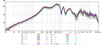
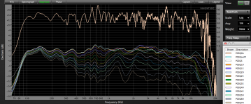
I had lost the polar response data for my 90 degree Paralines built in 2008, for a reference point to compare with my current SynTripP
http://www.diyaudio.com/forums/multi-way/262838-synergy-tripp-10-a.html
project using the same size enclosure (26.5" x 11.25" x 15" deep), I retested one of them yesterday. The top trace shows the equalized response with 1.5Hz resolution, the rest use 1/24 octave resolution (Fixed Point Per Octave, FPPO) with a smoothing of "9". The horizontal response is quite even, other than a narrow region centered around 1250 Hz were the dispersion gets wider- the opposite of what often happens with conical horns, which often exhibit "waistbanding", a frequency region that has more narrow dispersion, then wider. The interior height of the parallel walls of the horn is 9.75", the wavelength of 1390 Hz, so I'm not sure what about the Paraline/horn geometry that is responsible for the "midriff bulge".
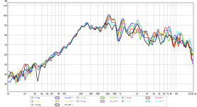
Vertical polars of the Paraline are a different story, exhibiting a classic pattern flip, 90 degree at 1000 Hz, but only 10 degrees at 16,000 Hz. The VHF vertical pattern is so narrow I had to take the polars twice, after realizing the mic, at six feet away was about 2.5" off from dead center, causing a 3 dB drop at 16,000 Hz!
Art
Attachments
Last edited:
Maybe the whole thing should be made of ellipses!
An ellipse has two points of focus.
you can put a driver (or two) at one focus, a horn (or two)
or a third driver at the other focus, and everywhere between
is hopefully so out of elliptical focus that you could hide a
few midrange injection ports.
But the air between the two points of focus is still a weighty
springy medium that has some acoustic impedance that must
be reasonably matched (both to each other and the ellipse)
at both ends or it affects the wave travelling through...
If you left horns and drivers off the second focus and just
expose a hole on both sides of the contraption, you could
radiate true omni. Though would be ragged response for
severe impedance mismatch to the waveguide reasons.
I proposed a horrible drawing of this back at #633
Last edited:
Ken,Danley's paraline measurement at #621 looks very smooth to 5K, and not bad above...
Yes, it looks smooth, because the measurements were smoothed.
Look at post #795 to see what the difference the type of smoothing and frequency resolution does to a response curve.
Art
Attachments
For comparison:
Raytrace of Patrick's example for the correctly shaped paraline...
Raytrace of the proposed smithagrain...
Raytrace of a confused mess...
Congratulations! You have invented the misalign.
I posted this before, but here's the radiation in a Sausalito Audio Works lens.
The curve is the same as the Paraline.
If anyone is wondering how the radiation works, this pic should help.
Note that there's no folds in the SAW lens, of course. Just a single 90 degree reflector.
- Home
- Loudspeakers
- Multi-Way
- Square Pegs