Very nice design! Can't wait to hear it! I wonder how similar the measured response will be to the simulation...
")
One problem: I don't have a suitable compression driver... I have a piezo tweeter and a mylar dome tweeter I can stick in there but it won't have the SPL's to match the two mids. I may try some GRS 87/8 sealed back mids first that I have on hand and see how that goes.
If you are building a paraline, you need
parabolas to be the full width of the exit.
Else bend them to a shape that properly
reflects and matches the size difference.
As you have it now, line sourced treble
will beam down the center of the larger
secondary triangle instead of filling it to
the edges.
You may need to turn that curve around
to a convex shape if you wish to keep the
internal horn filled as the rate of expansion
suddenly increases at the fold.
I'm not saying it will fail to play music.
Just that it won't utilize the internal horn
to full width, nor provide a fully illuminated
throat to an external horn that may follow.
Last edited:
X,I think Weltersys has some measurments of a Paraline and they are pretty ragged if he wouldn't mind posting them. They resemble my sim for the HF.
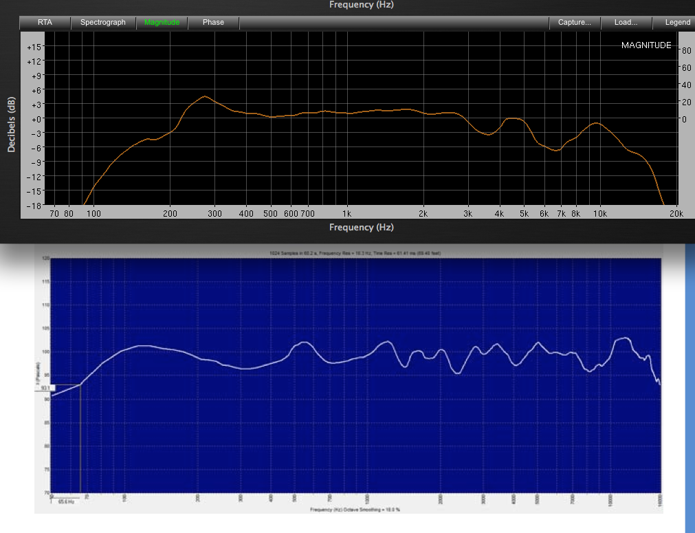
There are photos of my Paraline throat adapters in post #92, #207 has a photo of the finished cabinets, #314 compares the measurements of the Paraline to a conical horn, and post #589 compares my Dirty Dozen line array using twelve 25 cent speakers ($3.00 total driver cost) to the DSL SBH-10 using eight 5" coaxial drivers (probably over $1000 in driver cost). The Dirty Dozen response is much smoother than the SBH-10.
Note also that the SBH-10 used a frequency resolution of 16.3 Hz, if done at a resolution of 1.5 Hz (like my Paraline test) you would see about x10 more peaks and dips.
Art
Last edited:
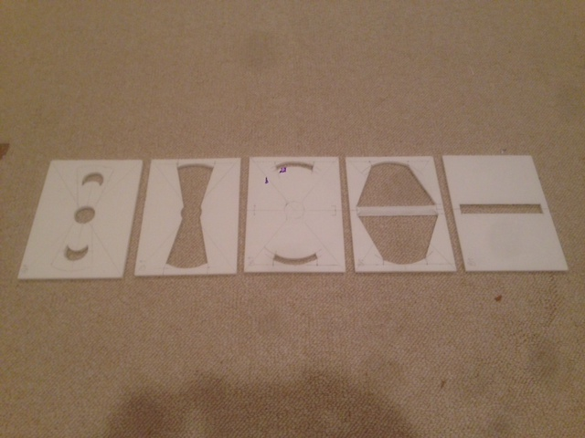
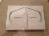
The way I see this it's simply a linear expansion from 1in to 6in over two paths with a single fold and a slot exit. It allows the mid drivers to be mounted very close to the HF source. The build in foam core was very easy to do by gluing each layer with hot melt and adding successive layers. 7 layers total including stiff cardboard backing for screw purchase and foam core spacer to keep mid surround from bumping back plate.
Attachments
X,
There are photos of my Paraline throat adapters in post #92, #207 has a photo of the finished cabinets, #314 compares the measurements of the Paraline to a conical horn, and post #589 compares my Dirty Dozen line array using twelve 25 cent speakers ($3.00 total driver cost) to the DSL SBH-10 using eight 5" coaxial drivers (probably over $1000 in driver cost). The Dirty Dozen response is much smoother than the SBH-10.
Note also that the SBH-10 used a frequency resolution of 16.3 Hz, if done at a resolution of 1.5 Hz (like my Paraline test) you would see about x10 more peaks and dips.
Art
1)
2)
3)
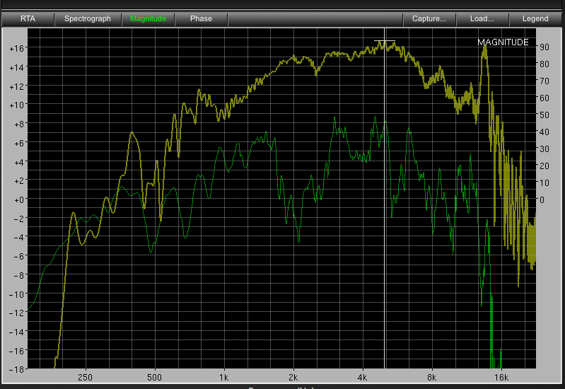
Note that Art says that "The Paraline is not particularly smooth, but has outstanding horizontal dispersion linearity on and off axis, and very narrow vertical pattern control, allowing multiple drivers to sum seamlessly.
The upper trace is a EV DH1A on a conical Maltese horn, the lower is a DH1AMT on a Paraline.
The driver's raw response may deviate slightly from each other, but the Paraline obviously does not appear nearly as "smooth".
Having replaced the Maltese horns with Paralines in my PA, the Paraline's response in multiples, after EQ, is far superior.
That said, I see no benefit (and many down sides) of the Paraline over a simple conical horn (as used in DSL's Synergy horns) for home use."
^^ Listen to Art, he's already been down this road...
4)
http://www.diyaudio.com/forums/multi-way/217298-square-pegs-59.html#post3725030
Someone mentioned my Paralines a few days ago, and put up a link. The measurement shown, I'm fairly sure, is 1/6 octave smoothed. The response with higher resolution is absolutely awful.
I used them for about a year and a half, but really they were only good for background music.....if that even. If I can find the higher resolution plots I'll post them.
I used them for about a year and a half, but really they were only good for background music.....if that even. If I can find the higher resolution plots I'll post them.
Someone mentioned my Paralines a few days ago, and put up a link. The measurement shown, I'm fairly sure, is 1/6 octave smoothed. The response with higher resolution is absolutely awful.
I used them for about a year and a half, but really they were only good for background music.....if that even. If I can find the higher resolution plots I'll post them.
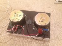
That is the feeling I get from reading posts and one reason why I built my first one out of foam core for under a $1 and 1 hr. Although my design deviates from a classical Paraline, the 180deg fold in such a tight channel with two 90 deg turns at the begining and end really seems to do a number on the frequency response. I am just starting to listen to it and make some initial measurments with a piezo tweeter stuffed into the 1in dia port hole. It sounds ok and measures terribly with lots of dips and peaks. The one good thing is that the mid injection port works really well extending down to 200Hz and going up to almost 2kHz using the two sealed back Goldwood 5in mids. If I had a decent CD it would have been simple to XO at 1200Hz or so.
This is by no means the aha moment I got when I listened to my full range Trynergy for the first time which I described as magical.
I have to say that this Paraline design is very compact as I have a 9in long horn that is only 1in deep and I am able to couple a pair of 5in mids into it very easily.
Attachments
Last edited:
Wrong shape. Therefore conclusions about performance are meaningless.
Worse than parabolic, you seem to have focused a bit to the center.
With bounces off the supporting structure, its not even a focus...
The second horn section is not properly filled, doing mostly nothing useful.
These almost random paths and lengths do not create a coherent wavefront.
Its not a paraline. Its not smithagrain. Its not a folded triangle waveguide.
The resulting exit pattern is a complete jumble of unscientific incoherence!
Other than having inexpensive fun, I think you've
slightly missed the best points this build had to offer.
If you can't draw the proper curve, then just stick to
a simple folded triangle that doesn't change expansion
rate before/after the fold. With a flat reflector slot.
That way should be almost idiotproof. Almost...
Attachments
Last edited:
Wrong shape. Therefore conclusions about performance are meaningless.
Worse than parabolic, you seem to have focused a bit to the center.
With bounces off the supporting structure, its not even a focus...
The second horn section is not properly filled, doing mostly nothing useful.
These almost random paths and lengths do not create a coherent wavefront.
Its not a paraline. Its not smithagrain. Its not a folded triangle waveguide.
The resulting exit pattern is a complete jumble of unscientific incoherence!
Other than having inexpensive fun, I think you've
slightly missed the best points this build had to offer.
If you can't draw the proper curve, then just stick to
a simple folded triangle that doesn't change expansion
rate before/after the fold. With a flat reflector slot.
That way should be almost idiotproof. Almost...
I think you've just volunteered us into building one of these contraptions.
For comparison:
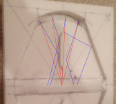
Raytrace of Patrick's example for the correctly shaped paraline...
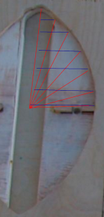
Raytrace of the proposed smithagrain...
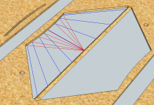
Raytrace of a confused mess...
Congratulations! You have invented the misalign.
Raytrace of Patrick's example for the correctly shaped paraline...
Raytrace of the proposed smithagrain...
Raytrace of a confused mess...
Congratulations! You have invented the misalign.
Attachments

Last edited:
Wrong shape. Therefore conclusions about performance are meaningless.
Worse than parabolic, you seem to have focused a bit to the center.
With bounces off the supporting structure, its not even a focus...
The second horn section is not properly filled, doing mostly nothing useful.
These almost random paths and lengths do not create a coherent wavefront.
Its not a paraline. Its not smithagrain. Its not a folded triangle waveguide.
The resulting exit pattern is a complete jumble of unscientific incoherence!
Other than having inexpensive fun, I think you've
slightly missed the best points this build had to offer.
If you can't draw the proper curve, then just stick to
a simple folded triangle that doesn't change expansion
rate before/after the fold. With a flat reflector slot.
That way should be almost idiotproof. Almost...
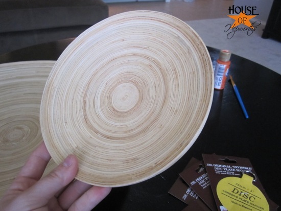
You can also build a radial horn by simply drilling a 1" hole in a wood plate and mounting your compression driver to it. Ikea has some bamboo plates that make good candidates for less than ten bucks.

Yes, you can indeed build a Synergy horn into a $10 ikea plate if you can live with it being omnipolar!
Wrong shape. Therefore conclusions about performance are meaningless.
Worse than parabolic, you seem to have focused a bit to the center.
With bounces off the supporting structure, its not even a focus...
The second horn section is not properly filled, doing mostly nothing useful.
These almost random paths and lengths do not create a coherent wavefront.
Its not a paraline. Its not smithagrain. Its not a folded triangle waveguide.
The resulting exit pattern is a complete jumble of unscientific incoherence!
Other than having inexpensive fun, I think you've
slightly missed the best points this build had to offer.
If you can't draw the proper curve, then just stick to
a simple folded triangle that doesn't change expansion
rate before/after the fold. With a flat reflector slot.
That way should be almost idiotproof. Almost...
I appreciate your feedback but would have to disagree with how you basically applied optical ray tracing to what is essentially a pressure waveguide. Imagine a conical flat horn going from 1 in to 6 in wide x 0.1875in deep over 9 in long. Now fold it in half and add a small brace akin to a spider in a CD phase plug or the struts in a Smith horn. How come no one complains about all those struts that would mess up the ray tracing. Or what about all the walls in a cellular horn? I maintain it is not ray tracing based to design this but concept of flow path lengths. The wavefront coming from the center will spread out radially and pass through the 180 deg fold. Just because the fold is curved doesn't mean the sound wave is focused like light rays in a magnifying glass. Sound waves do not propagate like a pencil like laser beam. The flat wall at the fold is not a reflector - what is important is the path length of propagation from the source. If I had stiffer material I would skip the brace but the foam core needed it there. I do see that to make a horn capable of higher SPL I need to use stiffer material as the FC vibrates and has some harmonic distortion contribution. Next build will be wood or plastic. This prototype was useful for me to see the tricks in construction and layout.
Last edited:
Yes, I should have drawn all the rays the same length rather than stop at the exit.
So you can better see and compare how the paraline descibes a line, smithagrain
describes an arc, and misalign describes a completely confused mess. Wood and/or
plastic upgrades will help, but won't change that sound waves do behave optically.
http://www.youtube.com/watch?v=KnjzJkBboc4
Nice example of plastic lens focusing sound and consequences of wrong vs right focus.
Last edited:
Regarding radial horn with a simple wooden plate. JBL tried that and
eventually had to tip the plate to a 45 degree angle and cut 5 petals
into it (radial Karlson) to get an acceptable result. Search Aquarius 3.
Apparently this idea has a history of not so easy to make sound right.
Avoid sharp impedance change all at one distance from the driver...
eventually had to tip the plate to a 45 degree angle and cut 5 petals
into it (radial Karlson) to get an acceptable result. Search Aquarius 3.
Apparently this idea has a history of not so easy to make sound right.
Avoid sharp impedance change all at one distance from the driver...
Last edited:
The Smith diffraction horn and the Paraline are both examples of how sound waves behave like optical waves at high frequencies, but more like laminar flow turning into an eddy current when the wavelength is long compared to the channel width.So you can better see and compare how the paraline descibes a line, smithagrain
describes an arc, and misalign describes a completely confused mess. Wood and/or
plastic upgrades will help, but won't change that sound waves do behave optically.
The Smith horn makes a rapid transition in vertical dispersion from a "beam" to "wide" because of the narrow vertical dimension (generally about the same as the HF driver exit) while the (standard) Paraline transitions form a nearly non-divergent beam to omni over a much wider frequency range due to the vertical height being large in relation to the wavelength of usual pass band.
Art
Last edited:
Nothing specific: The drawing was 25 inches tall and 48 inches wide.
Which is probably rediculously bigger than it needs to be. Also I drew
the layers 1/2inch thick. They should probably be less than 1/4inch.
The exit slot should have been only 1/2 inch wide, which means the
whole thing shouldn't have been taller than 24.5inches... So, its all
kinds of ways messed up (the drawing is). But the idea is still solid.
Just gonna to have to wing it on the specifics...
Find some sonotube you like. Make a panel about 1cm to 0.5in taller
than two sonotube diameters. Then draw a pair of 90deg (or whatever
coverage angle you wish) triangles, narrowing as they go away from
the exit slot. Then at some reasonable margin from the edges of the
panel, you need to draw two triangles back to the center to meet the
driver. Lastly you have to draw the lens that matches your triangles.
If the triangles are same, the curve is a flat line. Elsewise, you draw
lines that bisect the difference between one triangle's edge and the
other. And they meet somewhere way off the panel, but thats the
center of the curve you got to draw that will be correct at the outside
corners. As for the center, it might not make the optimum lens to draw
a simple circular arc, but its probably not far off.
If you want to figure lens bulge or squish, then you need to draw a
circle from the apex (another point somewhere off board) of the exit
triangle, to the edges of the exit slot, to visualize the curve of the exit
wavefront. Then the distance from the driver to the lens and back to
the wavefront should be the same in the middle as the outside edge.
When raytrace bounces and distances all agree, you've got your lens.
Probably overkill to worry about more than two or three points on the
lens curve, as most folks couldn't saw a curve that accurate anyway.
Now, I like the exit triangle to be 90deg so it can go in a corner and
seamlessly cover all the way to the walls. And I like the throat triangle
to be somewhat narrower, so the expansion rate can increase at some
stepped approximation of logarythmic. What that means in height to
width of the panel? I didn't rightly figure anything, but just eyeballed it...
Last edited:
Yes, I should have drawn all the rays the same length rather than stop at the exit.
So you can better see and compare how the paraline descibes a line, smithagrain
describes an arc, and misalign describes a completely confused mess. Wood and/or
plastic upgrades will help, but won't change that sound waves do behave optically.
Acoustic Lenses - YouTube
Nice example of plastic lens focusing sound and consequences of wrong vs right focus.
If you insist it acts like an optical ray trace explain to me what you think happens to your "rays" when they pass through a 180 deg right angle hair pin turn. The rays are hitting a perpendicular wall to the path as they squeeze through the curved slot - with your assumption of ray like behavior this would cause all the sound to bounce directly back to the source. Unless you have 45 deg angled reflectors at the bottom and top covering the curved slot - which most people don't do. So the sound is really just fluid mechanics and flow (oscillatorary flow) is getting pushed through the slot. High frequencies diffract around features that are of the same scale as the wavelength. The braces that I have which you show the sound bouncing off like a ray would only happen if the feature size is larger that the wavelength scale. 15khz half wave is 1.1cm. The braces are actually smaller than 1cm so in reality all the sound waves longer than 15khz just pass thru it like it wasn't there.
Your example on the YouTube link has water as the transmission medium. The speed of sound in water is 5x the speed of sound in air. As a result, the wavelength of sound in water is 5 times smaller than air. So objects of several cm length scale are large in comparison and the "lens" effect and ray tracing is valid.
An example of this can be seen with infrared light - it goes right through clouds because the water droplets that are in the clouds are smaller than the IR wavelength. (Assuming the IR is not in resonance with an IR molecular absorption line of water).
As my feature sizes for the 180 deg hairpin turn is based on sub 5mm thick channel features - the sound is behaving like fluid flow through a channel rather than waves reflecting like rays of light. It is a fluid dynamics problem.
Last edited:
You are totally missing the point that there are 3 dimensions.
In the vicinity of the foldback, only one of them is thin enough
to behave as-if a fluid. The other two are large enough that
optical rules become extremely relevant.
You are thinking in a phase plug where at least 2 and maybe
all three dimensions are small enough to act like a fluid. Yeah,
there where every feature is smaller than 1/4 wave, you can
ignore optics, maybe... Not every dimension is small like that
at the fold: Thickness yes, width no, length no.
So you got both sets of rules in play at the fold, and you have
to look at each dimension's constraint to determine which rule
is in effect. Yes it flows around because of the small dimension,
and reflects like a curved mirror because of the other two large
dimensions.
Last edited:
- Home
- Loudspeakers
- Multi-Way
- Square Pegs