staggerlee said:
is there a product at Homedepot or Lowe's?? Some sort of epoxy perhaps?
thanks,
gychang
Attachments
ronc said:There are better things than duct seal. Try the two part adhesive/filler. It gives strength and damping
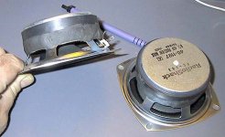
are u referring to 2 parts exoxy syringe type? Similar to pictured?
gychang
Attachments

I had no idea bracing was so critical. That's why these forums are so great, errors are quickly corrected.
Ron, do you mean the epoxy body filler panel beaters use for filling dents on motor cars?
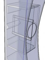
Would epoxying plywood braces from the back of the basket legs to the magnet be advisable? They would also reduce turbulence. The outer edges could be rounded or tapered.
A dodgy sketch to show what I mean, but over the basket legs, not the voids as shown here.
Ron, do you mean the epoxy body filler panel beaters use for filling dents on motor cars?
Would epoxying plywood braces from the back of the basket legs to the magnet be advisable? They would also reduce turbulence. The outer edges could be rounded or tapered.
A dodgy sketch to show what I mean, but over the basket legs, not the voids as shown here.
Attachments
ronc said:Its called metal weld or metal bond. It can be machined or ground. It provides a stronger frame and a damping action.
ron
thanks Ron, I know which one. This is a great help. For the Chang cabinet I want everything to be the best.
")
I have no doubt that with a powerful enough program all these variables can be fine tuned to a fare-thee-well, though I doubt such possibly exists yet outside NASA or similar,
Not really, all it takes is time and a fast enough number crunching potential. Every time you add a modifier to a program the computing cycle has to re-cycle to evaluate the new modifier.
A long time ago when PCs were first coming out i would evaluate them by a simple trinominal equation in which there was a single known value and two unknowns. The amount of cycles was a known and the time it took to find an answer was the relative "speed" factor. The early puters could take anywhere between 15 seconds to several min. Today its impossible to use that base as its an instant result.
The more cycles a puter has to perform the greater the time. A program at NASA is actually no more involved than many commercially produced programs, but they have access to faster puters.
ron
Chang query.
The triangle divider to prevent crosstalk has no dimensions, it looks like about half a litre. How critical is the volume of the Chang chamber?
A driver brace in place of that with some holes only in the front half would offer better segregation. I was thinking enough random holes to equal the area of the driver.
Would it be wise to make the length of the slot vents adjustable for tuning or are you pretty sure that part is correct?
Is it worth rounding over the edges of the slot vent or is the port velocity too low to worry about?
Re: Chang query.
I was thinking about combining the brace and "triangle", OzMikeH idea seems reasonable, any concerns from the experts?
gychang
OzMikeH said:The triangle divider to prevent crosstalk has no dimensions, it looks like about half a litre. How critical is the volume of the Chang chamber?
A driver brace in place of that with some holes only in the front half would offer better segregation. I was thinking enough random holes to equal the area of the driver.
Would it be wise to make the length of the slot vents adjustable for tuning or are you pretty sure that part is correct?
Is it worth rounding over the edges of the slot vent or is the port velocity too low to worry about?
I was thinking about combining the brace and "triangle", OzMikeH idea seems reasonable, any concerns from the experts?
gychang
An externally hosted image should be here but it was not working when we last tested it.
Re: Chang query.
So it doesn't!
Same as a BR except amplified by the vent's gain BW.
Hmm, its main purpose is to keep standing waves from developing between the vents as well as back to the driver, so I don't see how a ventilated driver brace is going to do both if I'm understanding you.
I haven't simmed it, but obviously it's only going to be as accurate as the input/software, so if you're willing to make it adjustable, then by all means do since it's one more way to help you fine tune it to the room.
No, the air mass 'slug' in the tapered section will damp it to a very low speed, though it might be worthwhile to do it to stop standing waves from developing across the inlets above ~718 Hz.
OzMikeH said:The triangle divider to prevent crosstalk has no dimensions, it looks like about half a litre. How critical is the volume of the Chang chamber?
A driver brace in place of that with some holes only in the front half would offer better segregation. I was thinking enough random holes to equal the area of the driver.
Would it be wise to make the length of the slot vents adjustable for tuning or are you pretty sure that part is correct?
Is it worth rounding over the edges of the slot vent or is the port velocity too low to worry about?
So it doesn't!
Same as a BR except amplified by the vent's gain BW.
Hmm, its main purpose is to keep standing waves from developing between the vents as well as back to the driver, so I don't see how a ventilated driver brace is going to do both if I'm understanding you.
I haven't simmed it, but obviously it's only going to be as accurate as the input/software, so if you're willing to make it adjustable, then by all means do since it's one more way to help you fine tune it to the room.
No, the air mass 'slug' in the tapered section will damp it to a very low speed, though it might be worthwhile to do it to stop standing waves from developing across the inlets above ~718 Hz.
You beat me to it Greg...
The chamber volume isn't 'critical' in that the slightest deviation won't destroy the sound -I made sure there was some flexibility for adding bracing. Vent velocity is low -you can round them off so long as the dimensions remain the same: it certainly wouldn't hurt. The back loading works over a relatively narrow passband. You can retune the cabinet / shape the FR to taste by adjusting the CSA & length of the vents like any MLTL or BR box. I simply went for what I considered to be the optimal max flat alignment in 1/2 space, and Ron optimised the loading from there with the curved front.
The chamber volume isn't 'critical' in that the slightest deviation won't destroy the sound -I made sure there was some flexibility for adding bracing. Vent velocity is low -you can round them off so long as the dimensions remain the same: it certainly wouldn't hurt. The back loading works over a relatively narrow passband. You can retune the cabinet / shape the FR to taste by adjusting the CSA & length of the vents like any MLTL or BR box. I simply went for what I considered to be the optimal max flat alignment in 1/2 space, and Ron optimised the loading from there with the curved front.
Re: Re: Chang query.
I'm new to this so please bear with my half baked solutions to half understood concepts.
I don't understand which standing waves.
from the vents back to the driver?
from the back (panel) to the driver?
IF THE FORMER:
I have trouble visualising how standing waves can form diagonally across a box. If that is the case perhaps an angled 8 inch brace in the path of those waves in the middle of each "half box" would help.
IF THE LATTER:
You could get some drastic reduction of crosstalk if you put the unholey brace in (now that I see the scale on the sketch I understand there is no need for holes), then put 2 deflectors angled backward to 1: diffuse the back wave off the driver 2: further convolute the path from one vent to the other.
see sketch.
edit: whoops, heres the sketch.
GM said:
Hmm, its main purpose is to keep standing waves from developing between the vents as well as back to the driver, so I don't see how a ventilated driver brace is going to do both if I'm understanding you.
I'm new to this so please bear with my half baked solutions to half understood concepts.
I don't understand which standing waves.
from the vents back to the driver?
from the back (panel) to the driver?
IF THE FORMER:
I have trouble visualising how standing waves can form diagonally across a box. If that is the case perhaps an angled 8 inch brace in the path of those waves in the middle of each "half box" would help.
IF THE LATTER:
You could get some drastic reduction of crosstalk if you put the unholey brace in (now that I see the scale on the sketch I understand there is no need for holes), then put 2 deflectors angled backward to 1: diffuse the back wave off the driver 2: further convolute the path from one vent to the other.
see sketch.
edit: whoops, heres the sketch.
Attachments
Re: Re: Re: Chang query.
wow..., very interesting idea to get the driver brace and help distribute the sound waves...
gychang
OzMikeH said:
I'm new to this so please bear with my half baked solutions to half understood concepts.
edit: whoops, heres the sketch.
wow..., very interesting idea to get the driver brace and help distribute the sound waves...
gychang
Attachments
Thanks Greg, Of course it may actually be a really bad thing, I have no idea yet.
Compared to the Bruce with only 2 parallel panels this has so many it's concerning me. Probably nothing to worry about, it's just my brain being used to so many angles.
You box is coming along nicely, keep the pictures coming.
Compared to the Bruce with only 2 parallel panels this has so many it's concerning me. Probably nothing to worry about, it's just my brain being used to so many angles.
You box is coming along nicely, keep the pictures coming.
The standing wave in question is the vertical mode of the back chamber, which we don't want developing between the two vents. GM warned me about this potential problem about a year ago when he saw the rough layout of another (stillborn) box I was mooting. That's why I put in the triangular deflector between the two vents (its size isn't critical, just so long as it masks the depth of the vents from each other) in an attempt to avoid this problem & noted that there are plenty of other ways to achieve the same too. A holy horizontal brace instead of the deflector, with the rear couple of inches left undrilled to prevent a standing wave between the two vents, would probably work, though I like the angle of the deflector myself. Whatever is used, remember, KISS is good.
Thanks Scott, i replied.
Let me work on this, i believe the pressure is supplied from the 167? I have never worked with the 167 but as any fostex driver there is an above average overall performance.
As stated in my email. i am deeply involved with my thermal studies but i will find the time to optimize the wave form to achieve a balanced condition for this cab.
With the 8" driver and cab you designed around 12' distance from the driver to the listener and both directly aimed at the listener it should be a bit greater than you think in the lower frequency reigon, not boom, but more defined and powerful(energy is focussed at at centerline)
ron
Ha Ha, found you.
I got the wood.
I've only a bit of fine tuning to do to my plans.
Then I/m going to build the FE206 Chang, with FT17 super tweeter.
I think most of my questions have been almost answered on this thread if I can sort them out (100 pages at double sided printing)
A couple of initial questions :-
where should the tweeter go as shown below?
What and specificaly where should I line the expansion chamber?
The top and bottom deflectors are at 43 degrees, could these be at 45, it would make construction easier.
The design below is derived from Scotts basic Chang with extra info he provided me with.
Plan of action.
With the angled deflectors the curved front Chang can be cut from 3 8x4 sheets of chosen timber material. In my case 18mm MDF.
The curved sides will be ct by router using a template, this then allows me to use the off-cut to give extra ridgidity to the side and also keep up the art-deco appearance.
The back, top, bottom, I'm going to make as one piece and use expanding foam to fill the gap behing the deflector, this will help kill some panel resonances, while keeping them down in wieght.
Did some carboard cutouts (well drew a rought outline on some 6x2 MDF and placed them approx 240mm apart, footprint similar to my FE166's just a nadges taller.
Main problem before there all finished is trying to explain to her ladyship what I was/am doing.
When they are finished and done in gloss black with silver grill, she'll love them cos they'll match the telly, untill then excuses, lies etc on a postcard.
Attachments
- Home
- Loudspeakers
- Full Range
- Spawn of Frugel-Horn