The fact that noise is largely random in nature is precisely "here or there"; that is what distinguishes it from distortion in terms of theory, measurement and listening. Distortion, by definition, is signal-related. Noise is not. There is a small overlap if noise is signal-modulated. In order to understand the join, you first have to understand the dichotomy.
That overlap is where the fun begins - let's say the 'intrinsic' noise is essentially random in nature. But, because of a "deficiency" of the amplifier this noise is precisely modulated in volume by some factor, by the envelope of the audio signal. So what do we have then?
The pro world sees things differently it seems - from the Rane Pro Audio Reference, http://www.rane.com/par-d.html:Distortion, by definition, is signal-related. Noise is not.
distortion Audio distortion: By its name you know it is a measure of unwanted signals. Distortion is the name given to anything that alters a pure input signal in any way other than changing its size. The most common forms of distortion are unwanted components or artifacts added to the original signal, including random and hum-related noise. Distortion measures a system's linearity -- or nonlinearity, whichever way you want to look at it. Anything unwanted added to the input signal changes its shape (skews, flattens, spikes, alters symmetry or asymmetry, even if these changes are microscopic, they are there). A spectral analysis of the output shows these unwanted components. If a piece of gear is perfect, it does not add distortion of any sort. The spectrum of the output shows only the original signal -- nothing else -- no added components, no added noise -- nothing but the original signal. See the RaneNote Audio Specifications
Not so, many SS amps today have more distortion prior to 1 watt and lowers as power increases, unless the mbl is a cheap under bias design ...
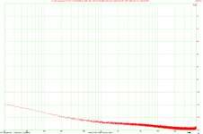
Now it is me who asks for the link . But not any link to THD+N vs. frequency plot. No need to see noise higher than distortion at low power.
The fact that the two are frequently presented as a single entity doesn't help matters. And, from my point of view noise is distortion, it is signal injected by the playback mechanism which is not part of the original waveform, the fact that it is largely random in nature is neither here nor there - distortion is distortion ...
So what is better - the design that has such low non-linear distortion that it rises from noise no sooner than somewhere at 10W, with noise level about -100dB re 2.83V unweighted over 20kHz.
OR
The design with noise level about -80dB re 2.83V unweighted over 20kHz, much higher non-linear distortion that dominates from some 100mW above noise, but is claimed to have superbly clean first watt?
Obviously the first, the second is only useful if it masks some subjectively more obnoxious, lower level fault ...
Yes, thank you. But the 2nd is the one that would have a THD+N plot rising with amplitude and at a first look it would have lower distortion at low power.
134mW (you can read it from the image), 6.8 ohm.
I have digged out the board from the amplifier grave, just to show something. Normal is below 0.001% at 100mW. There are some Messiahs that like to speak about high distortion at low levels, these stories might have been true in the seventies or eighties. Or for a cheap underbiased design.
Pavel, I'm guessing tht these days you don't see much of mainstream audio inside.
MOST of it is underbiased, and especially the HT, 5 or 7 channel gear. With those flimsy "heatsinks", actually aluminium plates with soldered-on fins about 0.5 mm "thick", how else could it be?
Of course, it also depends on what one consideres as undrbiased, but to me, circa 25 mA per single tranny is definitely underbiased.
But they did drive the prices down ...
For that I would buy you a pint of cider and maybe two . This makes your idea clear . I would say with less currant more feedback would be a reasonable thing to do .
A pint of cider would be lovely, two even more so, but only assuming we have like 2 hours to discuss matters. Before lunch, that is.

I use 100 mA with MOSFET's . It seems it is as Hitachi said about optimum . They are weird in being usable with zero bias ( circa 3 mA typical ) . Sort of washed out but almost OK .Contrary to Douglas Self's teaching gain doubling is not a major problem if bias is this high . He argues no amount of adjustment over comes the imprecise biasing of the MOSFET's . Equally setting it too high creates the muddy sound sometimes associated with MOSFET's . It could be said setting a bipolar amp this high is a deliberate attempt to have the worst possible amplifier if a technical believer . This ignores how we hear . I would suggest the 2.2 watts is already above the threshold and WE then become the MAJOR distortion problem in the system . Set it higher still to create serious heat problems . 2.2 watts is about right .
I would think that if we start being the problem, I've done my homework. I see it this way - with 2.2W/4 Ohms, even someone with 4 Ohm speakers will likely spend most of his listening time in pure class A domain. I've read somewhere that in reality most of us listening in our rooms spend over 90% of that time using 1W or less. In my case, even assuming the minimum impedance of my speakers, which is 6.5 Ohms, I have like 3.5W of pure class operation, which I assume will raise the ante from 90% to over 98%.
This more or less corresponds to Otala's 600 mA of bias in his old amp of 1974. He postulated that the class A region of operation should extend to -17 dB of nominal power, so his amp ran at 2.9/5.8W into 4/8 Ohms in pure class A. In its day, it simply sounded WAY better than most, a relatively low power level of 25/50W into 8/4 Ohms notwithstanding.
As for the sound turning "muddy", rest assured, exactly the same thing will happen to a BJT output stage if you overdo it. This is the point at which you need to turn it down a bit, because you won't be gaining anything, but will start losing definition and focus. Because there is no single set limit to the emergence of this effect, I always say 110-130 mA per output trannie is about right, but it does vary, and you do have to listen for it yourself.
Over my old Quad 303 I would expect a more detailed sound from your amp ( the class A bit ) . The Quad is so dam near perfect that's all I would expect . Drive my Maggie's harder and say goodby to them . The Quad is very gentle with speakers . The Krell is not my cup of tea I should say . However I suspect it has always been rich people who have shown them to me . They seldom seem to get hi fi to work well . Jimmy Hugues's Krell was very OK .
Most amps measure like op amps I find . The first watt is a great story . Alas hard to say it tells me much . Respecting it is good sense , build to optimizes this ( a La Dvv ) . The Hypex has very good sub 1 watt . In fact it goes into noise before showing a great change . Noise is a storm in some ways when class D . It took me a month to build a test rig to see that . Also the switch-mode confused the problems . I am tempted to say don't use the switch-mode . I had to because space was limited . As you might remember I call amps like this Cake Mix . I have modified the Hypex and built systems around it . My Cake Mix uses free range eggs perhaps ? I haven't listened to it yet because some mechanical engineering needs to be right first . Christmas would be ideal . I solved the switch problem . Plan A done better .
We should always bear in mind that this is a class AB topology we are using to force it into a higher bias regime. Therefore, there will be a limit.
Pavel, I'm guessing tht these days you don't see much of mainstream audio inside.
MOST of it is underbiased, and especially the HT, 5 or 7 channel gear. With those flimsy "heatsinks", actually aluminium plates with soldered-on fins about 0.5 mm "thick", how else could it be?
Of course, it also depends on what one consideres as undrbiased, but to me, circa 25 mA per single tranny is definitely underbiased.
But they did drive the prices down ...
I agree, but I thought we were speaking about high end here, not about commercial low-fi. I use as a rule of thumb 25mV per Re for BJT output devices, that means for 0.22 ohm Re the idle current per pair is about 113mA. My old amp digged out from amplifier grave box has 2 pairs of MJL21193/4, so it is biased at about 226mA total.
I agree, but I thought we were speaking about high end here, not about commercial low-fi. I use as a rule of thumb 25mV per Re for BJT output devices, that means for 0.22 ohm Re the idle current per pair is about 113mA. My old amp digged out from amplifier grave box has 2 pairs of MJL21193/4, so it is biased at about 226mA total.
Well, not really high end only, rather high end as well.
Could I trouble you with a request? The amp you mentioned, could you post its schematics? I am very curios.
Also, perhaps you could post your new ->BJT<- work, or give a link for it? If you have any, of course, you may have gone over to the MOSFET camp.
This paper discusses the "harmonic multiplication" effect at length. You would need to manually treat the 10% or more open-loop distortion cases with their equations since most of the cases they show start at 1% or less.
http://www.its.caltech.edu/~musiclab/feedback-paper-acrobat.pdf
Both of these guys are strongly invested in the "hearing above 20kHz" stuff. If you read Jerry's CV on his Wiki page you might be surprised.
There's also an excellent treatment of the subject in Bob Cordell's book, which boils basically down to what jcx posted above.
Jan
Could I trouble you with a request? The amp you mentioned, could you post its schematics? I am very curios.
It is more or less a predecessor of this
PA4 power amplifier
but only a functional sample with 2 pairs of output devices, only 2 x 27V supply voltage, small heatsink etc. This first sample had sub-optimal pcb and it was completely re-designed, regarding ground returns of supply rail bypass 220uF capacitors.
Please feel free to visit my photo gallery here
Power amplifier 2 x 300W - My Photo Gallery
Dvv . I think a 130 mA current gives about 0.27 watts class A or did I misunderstand JLH ? As you use triple outputs that is about 0.8 watts @ 8R ( 0.4 W @ 4R ) . That would be very OK .
My little amp's 0.7A to meet a 8 watt criteria . 1.15 A in Self's book is a comfortable 20 watts .
My little amp's 0.7A to meet a 8 watt criteria . 1.15 A in Self's book is a comfortable 20 watts .
Last edited:
130mA of output bias for a peak ClassA output of 260mApk does indeed give 0.27W into 8r0 of maximum ClassA.
Using a doubled output stage give 4times the ClassA power.
Using a 3pair output stage gives 9times the ClassA power.
using a 10pair output stage gives 100times the ClassA power.
9times 0.27W is 2.4W of ClassA
Using a doubled output stage give 4times the ClassA power.
Using a 3pair output stage gives 9times the ClassA power.
using a 10pair output stage gives 100times the ClassA power.
9times 0.27W is 2.4W of ClassA
the Cordell feedback thread had a number of pages on Baxandal "harmonic multiplication"
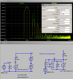
I did my usual simmed demonstration for a 10% "pure square law" gain device:
http://www.diyaudio.com/forums/soli...erview-negative-feedback-287.html#post1875719
here is that sim reworked with ~ 1% open loop 2nd order distortion, and with 40 dB loop gain negative feedback
you can see the new 3rd harmonic in the yellow fft harmonic peaks, it is created by the negative feedback around the "pure square law" behavioral I source
@ -108 dB this new distortion product would be at or below the human hearing threshold in a anechoic chamber for most loudspeakers < mid 90s dB SPL/W sensitivity at the "First Watt" drive level under discussion
the added E1 gain block in the feedback circuit only uses Av=20 because I credited the feedback loop with the gain of 5 from the output device since the closed loop gain is 1 for the feedback circuit
Attachments
Last edited:
It is more or less a predecessor of this
PA4 power amplifier
but only a functional sample with 2 pairs of output devices, only 2 x 27V supply voltage, small heatsink etc. This first sample had sub-optimal pcb and it was completely re-designed, regarding ground returns of supply rail bypass 220uF capacitors.
Please feel free to visit my photo gallery here
Power amplifier 2 x 300W - My Photo Gallery
Thank you, Pavel.
- Status
- Not open for further replies.
- Home
- Member Areas
- The Lounge
- Sound Quality Vs. Measurements