Dvv . I think a 130 mA current gives about 0.27 watts class A or did I misunderstand JLH ? As you use triple outputs that is about 0.8 watts @ 8R ( 0.4 W @ 4R ) . That would be very OK .
My little amp's 0.7A to meet a 8 watt criteria . 1.15 A in Self's book is a comfortable 20 watts .
Er, ... not quite, Nige. 4 x 130 mA is a total of 520 mA, which works out to exactly 2.15/4.3 Watts into 4/8 Ohms.
Otala's amp used a total of 600 mA of bias current, which works out to 2.9/5.8W into 4/8 Ohms.
Your little amp's 700 mA works out to 3.9/7.8W into 4/8 Ohms.
Self's 1.15 A is 10.5/21W into 4/8 Ohms. In my view and experience, too much, unnecessarily so, although I do not doubt he would produce a lot of maths to prove he's right.
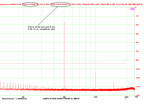
Yes, thank you. But the 2nd is the one that would have a THD+N plot rising with amplitude and at a first look it would have lower distortion at low power.
Yes rising thd or flatline thd with power output is considered to have more natural sonics , specially on high sensitivity speakers, we have to balance measured results with sonic acuity ....
I will post up links when i get a chance ...
Er, ... not quite, Nige. 4 x 130 mA is a total of 520 mA, which works out to exactly 2.15/4.3 Watts into 4/8 Ohms.
Otala's amp used a total of 600 mA of bias current, which works out to 2.9/5.8W into 4/8 Ohms.
Your little amp's 700 mA works out to 3.9/7.8W into 4/8 Ohms.
Self's 1.15 A is 10.5/21W into 4/8 Ohms. In my view and experience, too much, unnecessarily so, although I do not doubt he would produce a lot of maths to prove he's right.
80 watts of Class-a bias works for me on a 4 pr output stage or 8 if fets, 8 watts on a 3pr would be the minimum for great sonics ....
Last edited:
Yes rising thd or flatline thd with power output is considered to have more natural sonics , specially on high sensitivity speakers, we have to balance measured results with sonic acuity ....
I will post up links when i get a chance ...
We who play with topologies in a real world have plenty of possibilities to do so
")
The problem here is that people confuse THD with THD+N, and noise with non-linear distortion.
We who play with topologies in a real world have plenty of possibilities to do so
The problem here is that people confuse THD with THD+N, and noise with non-linear distortion.
Although one has to wonder, what's more realistic, a graph of THD only with no noise (impossible in real life), or a graph which includes noise, since it exists anyway and our ear cannot and does not distinguish between the two?
Even when discussing topologies, one has to wonder. For example, "revving" up one's input stage by increasing the input pair bias from say 1 to 1.5 mA, to obtain better performance, is all nice and fine, but one needs to balance that against inscreased noise level in that same stage.
My point is, noise is a realistic existing factor, like it or not, and it depends on several factors, ALL of which also influence our design choices. We can't just wish the noise away, we have to worry about it as much as about everything else.
I would be more concerned with specifications quoting AVERAGE THD within the audible spectrum. Averaging anything tends to swallow up possibly nasty peaks which may occur under dynamic conditions. If your THD is 0.001% 90% of the time, it could well be like 1% 5% of the time, and on average you'd still have like 0.05% THD.
I will easily agree that spectrum analysis is a most useful tool, even one we can't really go without, both for noise spreading and harmonic distortion decay, but as ever, nothing is ever reducable to just one or two aspects only.
As for being able to hear sound up to -20 dB below the integrated noise level, I must admit I am very sceptical about that. If noise is 10 times louder than what we want to hear, I'd say it is drowning in noise. I could be wrong, of course.
the "hearing below the noise floor" thing is sometimes misrepresented but PMA is being careful in specifying the Integrated Noise number - the RMS sum over the full audio bandwidth
we hear in narrower "critical bands" of ~100 Hz in the low bass to ~20% of center frequency higher up
games can be played by putting larger noise components down low where our hearing is less sensitive and listening for say a 3 kHz tone
an expample is pink noise - falls by 30 dB over the full audio bandwidth while giving an impression of ~ equal loudness vs frequency to our perception
at low SPL levels frequency masking can be approximated by 4th order slopes - noise an octave away has to be ~24 dB louder to perceptually hide the signal in a critical band
Last edited:
Yes, games can be played in this distortion business - the mind is always striving to make sense out of chaos, so the slightest pattern in what is otherwise random will stick out like the proverbial. The thing is, the goal of audio is at the other end, we don't want any sound not related to the audio signal to stick out, it needs to not be there at all, or to be masked. Or, to be so distinctively "different" in character that the mind can easily filter it away as not being relevant. A good example of the latter is playing some music, and it starts to rain outside - my goodness, noise levels have gone through the proverbial roof!! But, that good ol' brain of ours does a good disconnect of the 2 sound sources, we can happily keep listening to, and appreciating the music.
In fact, the latter is exactly why the highest quality replay allows "terrible" recordings to be enjoyed - the distortion and noise of the recording itself is so well reproduced that the mind 'sees' that it's not part of the musical event, and has no difficulty compartmentalising it ...
In fact, the latter is exactly why the highest quality replay allows "terrible" recordings to be enjoyed - the distortion and noise of the recording itself is so well reproduced that the mind 'sees' that it's not part of the musical event, and has no difficulty compartmentalising it ...
Last edited:
130mA of output bias for a peak ClassA output of 260mApk does indeed give 0.27W into 8r0 of maximum ClassA.
Using a doubled output stage give 4times the ClassA power.
Using a 3pair output stage gives 9times the ClassA power.
using a 10pair output stage gives 100times the ClassA power.
9times 0.27W is 2.4W of ClassA
Thanks Andrew . That's worth knowing .
Looking at feedback .
DF 96 told me some time ago to look at the problem as pure polynomials . Truly with the simple valve amplifier I was working on at the time you could . Sure enough everything was there . The problem being when 5% THD it is easy to think the - 65 dB stuff is noise . Add feedback and get a magnified view . This is where a valve amp becomes interesting . Maintaining a strict polynomial picture is difficult when applying feedback . Tried and tested ideas bring in the transformer and corrupt the easy maths . DF 96 gave me faith to say don't accept it is impossible . With some care and ideas usually only seen in primitive transistor amps I got distortion exactly like it was without feedback with a lower overall number ( parabola or whatever ) . Conventional feedback amps using valves seem more of a compromise .
My thoughts developed from that are . Music will mostly likely fit a fractal patten . A sequence with unknown starting point . Feedback requires we do not shift the numbers too much in timing terms . If so we get a big free lunch . The good news is this sequence is very accommodating to wrong numbers . For example if using 377/233 or 355/113 starting points the solution comes about >20 steps later . The fact that the wrong irrational sequence was fed in makes almost no difference . I would infer from that feedback needs to be fast and that is all . Well that is a fancy way of stating the obvious I guess ?
Wiki-theft .
A polynomial can either be zero or can be written as the sum of a finite number of non-zero terms. Each term consists of the product of a number – called the coefficient of the term – and a finite number of indeterminates, raised to integer powers. The exponent on a variable in a term is called the degree of that variable in that term; the degree of the term is the sum of the degrees of the variables in that term, and the degree of a polynomial is the largest degree of any one term with nonzero coefficient. Since x = x1, the degree of a variable without a written exponent is one. A term and a polynomial with no variables are called respectively a constant term and a constant polynomial; the degree of a constant term and of a nonzero constant polynomial is 0. The degree of the zero polynomial (which has no term) is not defined.
To solve the Thi sequence use these rules . 1/0 , 1/1 , 2/1 .... 0 is an acceptable input . Try 1000/1 , it is very nice if doing it on paper . It resolves in about the same number of step as 1/1 .
Last edited:
Feedback is always fast, unless the feedback path includes a delay line or a significant length of transmission line. I have not seen an audio ampliifer with either of those.nigel pearson said:My thoughts developed from that are . Music will mostly likely fit a fractal patten . A sequence with unknown starting point . Feedback requires we do not shift the numbers too much in timing terms . If so we get a big free lunch . The good news is this sequence is very accommodating to wrong numbers . For example if using 377/233 or 355/113 starting points the solution comes about >20 steps later . The fact that the wrong irrational sequence was fed in makes almost no difference . I would infer from that feedback needs to be fast and that is all . Well that is a fancy way of stating the obvious I guess ?
Last edited:
Fast might be faster than people suppose . The speed I was thinking of is the forward part . To me it is a loop so where you cut it . It makes no difference where the bottle neck is . I see feedback as a dog chasing it's tail . What is head and tail is not important . Dog is dog .
Someone said a great hi fi system plays mediocre sources well . Sorry my computer is playing up , finding stuff is proving difficult so no offense in not be more precise as to author . The truth of that statement can not be overstressed . In my experience most hi fi and especailly so called high end makes it almost impossible to listen to things that a transistor radio would make acceptable . My own system and a few I know of only make a poor quality source sound curiously coloured . I can not explain how a recording can change my Magneplanars into something that sounds boxy and as if there is an enclosure behind . I almost say how did they do that ? Equally I can hear depth and microphone pop on 1930's 78's . Not subtle . Rather better than most modern stuff in terms of using the microphones to best effect ( Bing Crosby etc ) . 1970's TV series seem the most boxy . In no way do I hate it . It just is curious . I couldn't make that sound if I tried . I can say many so called hi fi 's sound like 1970's TV all the time .
When CD came along I said I would rather watch TV . To blunt mostly I would regardless of what it is . My friend Oli has a Pioneer PL12D + Shure , NAD 3020 and Soviet era Spendor like monitors ( Latvian ? ) . This system although not as open as mine has the discerning quality . I never felt a Linn system did ( especially after the break with Naim ) . The LP12 however is a great turntable. Not as much as admirers think ( try a Garrard 401 , same stuff and better ) .
That severely misleading picture is, sadly, far too common among audio enthusiasts. These hoary old chestnuts keep getting dragged out. It is difficult to kill a false meme!nigel pearson said:I see feedback as a dog chasing it's tail .
The true picture involves a loop of filters, not delays. Start with the right picture and then you might have a chance of understanding what is going on. Feedback delays can matter if you are making a high performance RF or microwave power amplifier, which is why RF often uses predistortion instead of feedback. Audio is quite different.
You make an excellent point there . And it would be hypocritical of me to say otherwise ( too long ) . The predistiorton part I hope everyone reads .
I have often said I distrust slewing ideas . Never to the point of saying I don't bother .
Maybe DF 96 has accurately pinpointed the real problem . Michael Gerzon was out on a limb saying filters could sound different . Now that seems crazy he would be doubted . His letter head saying Dept of Mathematics Oxford University possibly helped people listen .
It is said when something is impossible make it irrelevant . High slewing possibly is just that . A dominant pole helps . Make it super dominant within the needs of the amp .
Mr Dvv . How about you use that and reject some of your emitter degeneration ? I think it would still fit your concept rather well . My suspicion is your amp has room to do that . The PCB will not change . That is making the dominant pole truly dominant . Equally keeping the Q low might help ? Good question I think ?
For example when 47 R I doubt it need be more than 10 R ( or 0 R sometimes ) . If you have painstakingly done that ignore my idea .
Triple outputs are rather sneaky . I will definitely use than in the my proposed nasty amp ( I sent you that some ages ago , the person who wanted it seems to want to use my time better now ) . I proposed to use the daft version of a complimentary feedback pair . I have a hunch one who writes here sometimes does exact that J C ?
My next project which will not be paid is an amp using 211 valves and 1000V . It was requested by the late Tom Fletcher who died before it could be delivered . The output transformer is 14 K which seems rather high ( peaking about 3.8 R I would guess at that voltage ) . It uses cathode bias and hum bucking . I am told it is far from being a good amplifier and needs something ( gutless ) . The 211 is perplexing as it looks one of the easiest triode valves to drive . 60 V rms should do it and my previous design got 77 Vrms no load from the driver valve ( 30 used ) . I have read 211 encourages grid current when not asking for that . As far as I can see 20 mA should drive it without falling over . I might post a photo if allowed . I will my previous if it ever gets made . Is grid current a bad thing ? I think Williamson allowed a little ? His grid leaks were double the usual ? Without feedback the Williamson causes the last 1.5 watts to wobble . Effectively the current is a joint effort above 13.5 watts between the KT 66 and the driver valve . I think he was 19 years old when he designed that ?
I want a proper funeral in the ground please , C of E . 1000 V !
- Status
- Not open for further replies.
- Home
- Member Areas
- The Lounge
- Sound Quality Vs. Measurements