Of cause with my first "quick" prototype some years ago,
i had not observed high distorsion.
But i could not evaluate low and high frequency performance,
because parts were not bonded properly and the structure
was not very durable ... e.g.. it was not worth building a
proper cabinet for.
That's why i want to build a more solid one now.
You mentioned the ability of "bending wave" trancducers
to radiate sound below coincidence frequency, which is
normally high.
One of my questions concerning my current prototype is
up to which frequency it is able to operate in 1st bending mode.
Ideally over the whole listening range, but i am not as naive
to believe i can achieve that in the first attempt.
I am curious to see at which frequency propagation
of higher modes will start, comparable to "cone breackup" at
conventional speakers, and if the system is able to perform
in that "distributed mode" at higher frequencies giving
statisfying quality. I think, it is possible.
I plan to scan the membrane with a laser and project the motion
of the membrane to a wall to observe it.
Best
Warnaka loudspeaker (1966) operates above Fc. My polycarbonate membrane has Fc=5074Hz. He uses thick and light membrane. The only thing we can do is to increase Young modulus - we cannot increase thickness and mass (efficiency) but good that thickness is in third power so aerogel, carbon fiber, nanotubes is a way to go, and some anisotropic properties plus eventually what Paul Burton did - two exciters and crossover at Fc.
Interestingly Daniela claims MSW to be at Fc=80kHz. How's that possible?
Interestingly Daniela claims MSW to be at Fc=80kHz. How's that possible?
Hi,
i still think there are basically 2 concepts:
- Membrane flabby, excitation transversal
(Warnaka, Manger, Conventional ESL)
- Membrane stiff, excitation longitudinal
(MBL, My one ...)
If using flabby elastic material (foil), optionally pre-stretched,
excitation in longitudinal direction will cause distorsion
because of unharmonic oscillation.
The way to excite those structures is transversal.
Low frequency performance can be achieved with small
excursion but large area in those designs.
My approach (and MBL's too i think) is not pre-stretching but
"pre forming" of a stiff stucture. Movement at low
frequencies is harmonic for small excursion, in my prototype
there is no pre-stretching or pre tension.
Goal is to keep width and area of the membrane small, but
allow max excursion which is comparable to a conventional
dynamic speaker. Exciation of higher vibrational modes is
undesired at first.
Nevertheless coincidence frequency as high as possible
(far above the hearing range) is desirable in my approach too.
From my gut feeling i would estimate, that my transducer
will start to behave like a distributed mode bending wave
transducer somewhee above upper midrange.
Further commercial examples for bending wave transducers
are Walsh (Ohm), German Physics (DDD), Göbel ...
Best
Oh, it looks like I have calculated wrong critical frequency for my current membrane - now I've got 86204Hz. What can I do? I think easiest way is to buy 2mm FR4 double side laminate (fc=1300Hz), increase the gap and take a series of measurements, calculate power response, evaluate efficiency.
With carbon composite, 2mm thick I've got fc=400Hz. Could someone check? Above fc longitudinal coincidence radiator is more efficient than piston.
With carbon composite, 2mm thick I've got fc=400Hz. Could someone check? Above fc longitudinal coincidence radiator is more efficient than piston.
Hi,LineArray said:I plan to scan the membrane with a laser and project the motion of the membrane to a wall to observe it.
one may be interested in the amplitude of the displacement, even after the "triangulation" when working in the interesting higher frequency range. Others use vibrometers or at least fast laser triangulation sensors for that task.
Regards, Timo
I don´t know whether you have looked at the linaeum patents. Here both branches of the coil are in the magnetic field. When I was considering to build an FAL like flat diaphragm driver some time ago I stumbled across a very useful element for such a task: Drawn steel profiles with a rectangular triangle as cross-section.
Attachments
Yesterday I was trying with balsa wood and piezo exciter. It was terrible. I think piezo bends and produces high frequency resonances of about 10dB with high Q. I have a little problem with 0.25mm traces needed for a double side 2mm thick FR4 laminate. I have at home several possible materials to try:
1) 1mm balsa wood, Young modulus 1-6 GPa, Density 150 kg/m3
2) 2mm FR4 laminate, 16 GPa, 1900 kg/m3
3) 5mm Aerogel, 70MPa, 130 kg/m3
3) 2mm self reinforced polypropylene, 5GPa, 980 kg/m3
Self reinforced commodities were explored by prof. Ward from University of Leeds. Polethylene is prefered for higher stiffness and lower damping that is needed in a contrast to piston driver. More info can be found in:
"Mechanical and Acoustic Frequency Responses in Flat Hot-
Compacted Polyethylene and Polypropylene Panels"
May be it is worth a try to use magnet syystem with both bends of voice coil in magnetic field, something like rubanoid, but applied to bending diafragm like from his topic design. It will demand twice more magnets, but you will gain in sensetivity and linearaty, probably.
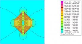
Here's a similar implementation in FEMM:el`Ol said:I don´t know whether you have looked at the linaeum patents. Here both branches of the coil are in the magnetic field. When I was considering to build an FAL like flat diaphragm driver some time ago I stumbled across a very useful element for such a task: Drawn steel profiles with a rectangular triangle as cross-section.
An externally hosted image should be here but it was not working when we last tested it.
It is using rectangular iron to get the magnetic circuit to a pair of very small gaps and seems to be very similar to what you are trying to do here for a field to drive a flat VC.,
Since this thread is working on 2D voice coils, you may find some interest in the thread that picture comes from -- a Linaeum / Rubanoid / JANUS50 discussion that has recently revived a bit:
http://www.diyaudio.com/forums/showthread.php?s=&threadid=69450
Hi,
of cause using both sides of the coil is preferable
with respect to efficient motor.
I had a design with a voice coil carrier using both sides,
but currently i prefer "wasting" one side of the coils for
better integration with coil and membrane, i do not know.
I auditioned a first attempt using only one sheet driven by
two coils today.
Positive:
- it IS a Fullrange system. There is Bass and highs are
really beasty, i had to eq with 0,27 mH 3,3 Ohm in parallel.
DC Resistance of Speaker is only 1,8 Ohm.
- there is some coloration in upper midrange
- distorsion seems in a sane area ...
Negative:
- low efficiency up to now (was expected)
- noise at higher volume (maybe connecting wire touches the
membrane, i will see)
- there is some coloration in lower midrange and "nasal" region.
Conclusion so far: No High End Speaker from the start ...
But i see potential (and work!)
Regards
Attachments
the panel seems to have a wide dispersion pattern,
even in the highs, even when listening about 45 degrees
of axis there is not much loss in brillance (if any ..).
Uniform dispersion and good output at the upper
end seem to be possible advantages compared to a
conventional fullrange speaker of same membrane area.
Even at that premature stage impulses like
attack from piano drum beats etc. were rather crisp
and realistic.
Listening to strings was awful sometimes, still too much
coloration.
LineArray said:the panel seems to have a wide dispersion pattern,
even in the highs, even when listening about 45 degrees
of axis there is not much loss in brillance (if any ..).
This is exactly what I experienced with this design:
http://www.diyaudio.com/forums/showthread.php?s=&threadid=80797&perpage=25&highlight=&pagenumber=3
Measurement gave a slower CSD than expected, so my conclusion was that it works like a DML speaker a'la NXT.
NXT Patent
I discovered this thread via jzagaja who emailed me with some questions about NXT's BMR technology and how it related to my own Sumo Aria panel speaker (over 20 years ago now) and the Podium panel.
I haven't had time to read the whole thread - it is quite long now. But it does look like you are embarked on something quite interesting.
I used to be NXT's Intellectual Property Manager, and I thought you might like to look at a patent application which I suspect you may not know about, particularly as it has a very uninformative title, designed to avoid getting the attention of competitors as far as possible.
It is all about in-plane compression drive of panels, and techniques to transform the compression waves into transverse bending waves which radiate sound. It was based on a serious piece of empirical research and modelling by Denis Moorcroft (of DNM fame) and Dr. Nick Hill, one of NXT's senior scientists.
If nothing else, it may give you some pointers going forward.
Details: WO 03090496 "Acoustic Device" Azima, H., Hill, N., Moorcroft, D.
Enjoy!
Paul
Rountree Acoustics Ltd
www.rountree-acoustics.com
Thanks to Paul and Neil Charris I've found missing connection between travelling wave and bending wave. Direct link to the said patent:
http://www.wikipatents.com/gb/2400264.html
http://www.wikipatents.com/gb/2400264.html
Below link kindly provided by Christien Ellis shows directivity of a DML:
http://tinyurl.com/d3jl8d
Sorry for a typo - not Neil Charris but Neil Harris.
http://tinyurl.com/d3jl8d
Sorry for a typo - not Neil Charris but Neil Harris.
Hello,
@Paul Burton: Thank you for the information, i am currently
reading the patent.
@jzagaja: The animated polar plot is very instructive and
matches my experience with my own DML panel.
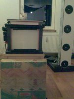
Now proudly like to present: The ugliest speaker built ever:
@Paul Burton: Thank you for the information, i am currently
reading the patent.
@jzagaja: The animated polar plot is very instructive and
matches my experience with my own DML panel.
Now proudly like to present: The ugliest speaker built ever:
Attachments

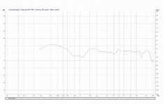
Now a quick measurement.
Around 1m distance about 45 degrees off axis.
Free air resonance of the driver is about 55 Hz, dependent
on suspension.
Time frame is too short to evaluate the bass response
of the speaker, but due to high Qts it sounds a bit
"fat and boomy".
Sounds different than a conventional dynamic fullrange
driver.
Sound does not change very much with listening position.
Listening is OK even at larger distances.
After some tweaking i can listen even to strings and voices
without getting hurt.
I have not expected to get that far with this prototype ...
Attachments
Hi,
i currently have no calibrated setting to evaluate
efficiency properly.
I would estimate in comparison ro other speakers
i own, that efficiency is below 80dB/W at 1m.
The proto's motor has an air gap which is 8mm wide ...
It was just designed for experimenting/development.
Next Proto will have a different motor:
- Air gap will decrease to ca. 1mm
- Stronger Magnets of double volume
- Double length of wire in the magnetic gap¨
Furthermore mass of diaphragm and stiffness
of suspension will be optimized.
I expect that efficiency will be in the range of
conventional dynamic speakers of same diaphragm
area (active area around 400cm^2).
A "high efficiency" version will be possible regarding
stiffness of suspension. There will be the same
compromises as with conventional dynamic speakers.
But it is difficult to have a conventional fullranger
of that size, having an upper frequency limit of
around 20 Khz with excellent dispersion up to the
top ...
Kind Regards
- Status
- This old topic is closed. If you want to reopen this topic, contact a moderator using the "Report Post" button.
- Home
- Loudspeakers
- Planars & Exotics
- Sketch For Bending Transducer (Prototype already built)