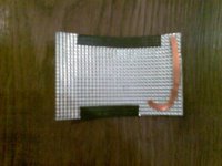
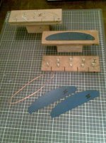
Checking materials with smaller than original piece
of AL:
- Edges of membrane mantled with textile
- Fragment of prototype coil glued to membrane
(16 Windings)
- Two membranes were bond together with lossy glue
to resemble the final structure of the transducer
Both textile and resin bonded coil introduce damping
to the membrane.
Membrane was knocked with finger nails, thai sticks etc. :
No metal ringing audible !
Several persons knocked the material and compared it
to a state of the art AL bass/midrange (Visaton AL 130).
Conventional midrange has still metal ringing sound,
new membrane sounds more like soft paperboard.
Guess i am on the right way!
Attachments

Hi,
i am very courious, because etching or printing is
an elegant way to make voice coils.
However old fashioned wire is very predictable in
electrical resistance, it is mechanically robust and
thermally resistant.
Wire can be bonded to the diaphragm using a
glue having properties under my own control like
elasticity and cohesion.
This is why i prefer copper wire for my current
prototype for simplicity.
Additionally i use the coils as damping elements
for the diaphragm.
But i guess you will use different membrane material
than i do ...
Best
The trick is to heat not the paper but the laminate with iron set to ···
Paper peels easily after few minutes. Some retouching is still necessary. Calculated resistance is 3.8Ohm. Tomorrow will etch and play some music. I'm thinking about some pattern between coils.
Paper peels easily after few minutes. Some retouching is still necessary. Calculated resistance is 3.8Ohm. Tomorrow will etch and play some music. I'm thinking about some pattern between coils.
Attachments
Hi jzagaja,
your print looks good, but i have a concern
regarding your design:
As far as i can see, the layers on each side run zigzag
in the magnetic field. While a certain layer running up
will experience a force in one direction, its neighbour
layer running down will experience a force in the
opposite direction.
When the number of layers running up and the number of
layers running down are equal, the forces acting on the
layers will cancel out each other and the resulting force
driving your voice coil(s) will be zero.
The membane will not move and remain in silence.
Maybe i overlooked something in your design, but this
is what i think will happen, when you use the magnet
assembly shown in your former post.
Best
")
Hi,
current changes its direction with the music signal right ?
And we want the force acting on the voice coil to follow
the music signal right ?
When forces on the layers cancel out each other, the voice
coil experiences no force and cannot follow the signal.
Current in the (each coils) magnetic field should flow in the
same direction in all layers.
Since you have two coils, left and right coil as a whole
should move in opposite direction, to achieve the intended bending motion.
Best
I have only one copper layer but anyway zig-zag is wrong and spiral is right - wire enters magnet path always from bottom side to the top?
In your sketch magnets are of the same polarity left and right side. Shouldn't be opposite if you want push inward and outward? Of course you can connect the second coil set out of phase.
At this stage my speaker sound quite nice on music (!) but produce enormous amount of distortion - centring is a tricky part.
jzagaja said:This is how it should look right?
Yes, that blueprints look good.
You are right, either you change the
polarity of the magnetic field for left
and right motor or you connect left and
right voice coil out of phase.
Concerning distorsion:
How does your Membrane look like ?
Are you using 2 Membranes like i suggested ?
Maybe you have trouble because the energy
density in your air gaps varies due to the
bending of your magnet bearing. This may
cause a kind of motion which not uniform,
causing ripples or unwandet sharp bends ...
The driving force in the middle is much higher
that at the ends.
What kind of Material are you using as
Membrane ?
Best
How does your Membrane look like ?
Single rectangular 208x140x0,07mm, active area 208x80mm.
Are you using 2 Membranes like i suggested ?
Not yet because don't know how to do it well and gap is too thin.
What kind of Material are you using as Membrane ?
It looks like kapton-copper laminate. Today I've tried 0,5mm spiral coil but I overheated one side and got unequal impedance. Inductance is between 0,5 and 1 uH. Still getting 40-60% THD and looking where the are coming from. Plays significantly louder but impedance dropped too. Membrane is flabby and I'm pretty sure it doesn't rely on bending especially when stretched.
Hi jzagaja,
congratulations for your coils, i think you will manage
the problem with tolerances sooner or later ...
When you say "it does not rely on bending especially when
stretched" do you mean you want to implement a
flat membrane ?
I think in that case the kind of longitudinal excitation
is not the right way to go. Maybe you find a different way
of making it work than my current approach.
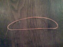
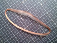
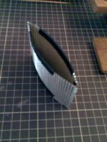
My approach is a rather stiff oscillating structure. First thing
i need is some kind of harmonic oscillator, where reset force is
proportional to membrane excursion
- at least for small excursions !
If the structure is not able to do harmonic oscillation,
high distorsion is inevitable IMO.
With my current approach of integrating voice coils and
membrane, a narrow magnetic gap is impossible, that's right ...
But there is enough place for strong magnets and thick pole
pieces on the other hand, so i can compensate for that
drawback.
Picture shows a mini model of the oscillator:
congratulations for your coils, i think you will manage
the problem with tolerances sooner or later ...
When you say "it does not rely on bending especially when
stretched" do you mean you want to implement a
flat membrane ?
I think in that case the kind of longitudinal excitation
is not the right way to go. Maybe you find a different way
of making it work than my current approach.
My approach is a rather stiff oscillating structure. First thing
i need is some kind of harmonic oscillator, where reset force is
proportional to membrane excursion
- at least for small excursions !
If the structure is not able to do harmonic oscillation,
high distorsion is inevitable IMO.
With my current approach of integrating voice coils and
membrane, a narrow magnetic gap is impossible, that's right ...
But there is enough place for strong magnets and thick pole
pieces on the other hand, so i can compensate for that
drawback.
Picture shows a mini model of the oscillator:
Attachments
- Status
- This old topic is closed. If you want to reopen this topic, contact a moderator using the "Report Post" button.
- Home
- Loudspeakers
- Planars & Exotics
- Sketch For Bending Transducer (Prototype already built)