@tiki
Since i do not rely on marketing my ideas, i can afford to
share them.
If anyone wants to try them out, he/she may do so.
Thats the aim of this DIY forum. If the posted idea is
unattractive to you, then that's the
way it is, you know. It does not bother me.
But i fear you may just want to discuss your own approaches.
If so, you can tell us e.g. what the specific advantages of your
TIMAG driver are compared to state of the art woofers.
We are curious. A patent itself is neither an advantage nor
can a patent substitute real advantages.
Like engineering power cannot lift up a relatively uncreative
design into a creative one.
I am discussing the design of a fullrange bending transducer in
this thread. And of cause there is substantive inspiration from
other members as you can see. Which is why i dislike your posts
in general, frankly speaking.
You are the only one beating words like a dead horse.
Yes i said "homogenoously driven large area".
If you like, substitute it by e.g. "operating in 1. transversal
mode" or any other term you like the most.
You talk about "almost pistonic" motion referring to ribbon
speakers in the motivation of your timag driver ?
Fact is: Force through diaphragm propagates very fast, due
to longitudinal excitation instead of transversal.
The MBL transducers are successful commercial products
demonstrating the applicability of the principle.
A barrier still to to be overcome by your design AFAIK.
My lifetime is simply too valuable to beat words like dead
horses. Do you want me to search for some dead horses in your
texts ?
There are lots of. Tiki you seem to be unaware of the extent
you benefit from other people being forgiving concerning
your own texts. That is your main problem. Please solve it
elsewhere and not in this thread, its enough.
Kind Regards
sometimes one can learn from the hobbyist:
http://www.youtube.com/watch?v=bvnyot6T-QQ&hl=de
Why it is useful to reduce the degrees of freedom of an
oscillating structure, if you want to use it as a loudspeaker
(and not as a demonstrator for chladni figures) ...

http://www.youtube.com/watch?v=bvnyot6T-QQ&hl=de
Why it is useful to reduce the degrees of freedom of an
oscillating structure, if you want to use it as a loudspeaker
(and not as a demonstrator for chladni figures) ...
In bending transducer we linearly gradate membrane thickness, changing bending stiffness and extend high frequency rollof - in Manger up to 80kHz. Now question is in which direction here? Common sense tells thicker at the middle.
Got some prices from Dupont. Kapton copper clad laminates:
1) DuPont Pyraflux LF, 610x935 mm, 156 Euro each, 75/35my Substrate/Cu - single or double side.
2) 25/35my, 8x A5 sheets, 90 Euro.
Got some prices from Dupont. Kapton copper clad laminates:
1) DuPont Pyraflux LF, 610x935 mm, 156 Euro each, 75/35my Substrate/Cu - single or double side.
2) 25/35my, 8x A5 sheets, 90 Euro.
Hi jzgaja,
you have looked up interesting materials ...
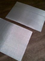
Currently i do not think about changing stiffness across
the width of the diaphragm.
If such modification seems necessary in the further
development i tend to modify stiffness by stamping an
appropriate pattern into the diaphragm.
See attached pics.
First i think about
1) how to design/integrate the voice coils
2) how to design the gasket (major construction problem)
3) how to design the suspension if not identical with the gasket
My current thoughts:
1) Wind 2 stretched rectangular coils and glue them between
the left and right edges of the sheets.
This way no additional VC carrier is needed. Diaphragm
acts as heat sink ... which should result in very high power
rating.
2) No Gasket ! Tolerate a slot on the bottom and the top
of the diaphragm. Edges of the slot are covered with
textile to minimize streaming noise at high excursion.
Leakage is accounted for in the Qts of the system and
dimensioning of the cabinet to be built.
3) Suspension can be formed as elastic bobbins below/ontop
of the voice coils, allowing proper adjustment of the coils
in the magnetic gap and well defined VC motion in one plane
only.
Since i have seen and heard the early prototype working, i tend
to solve those design an manufacturing issues first.
When necessary to go to different diaphragm materials i
would do that in a next step without changing the mechanical
principle after that principle is tested.
Please keep on sharing Your thoughts ...
Kind Regards
you have looked up interesting materials ...
Currently i do not think about changing stiffness across
the width of the diaphragm.
If such modification seems necessary in the further
development i tend to modify stiffness by stamping an
appropriate pattern into the diaphragm.
See attached pics.
First i think about
1) how to design/integrate the voice coils
2) how to design the gasket (major construction problem)
3) how to design the suspension if not identical with the gasket
My current thoughts:
1) Wind 2 stretched rectangular coils and glue them between
the left and right edges of the sheets.
This way no additional VC carrier is needed. Diaphragm
acts as heat sink ... which should result in very high power
rating.
2) No Gasket ! Tolerate a slot on the bottom and the top
of the diaphragm. Edges of the slot are covered with
textile to minimize streaming noise at high excursion.
Leakage is accounted for in the Qts of the system and
dimensioning of the cabinet to be built.
3) Suspension can be formed as elastic bobbins below/ontop
of the voice coils, allowing proper adjustment of the coils
in the magnetic gap and well defined VC motion in one plane
only.
Since i have seen and heard the early prototype working, i tend
to solve those design an manufacturing issues first.
When necessary to go to different diaphragm materials i
would do that in a next step without changing the mechanical
principle after that principle is tested.
Please keep on sharing Your thoughts ...
Kind Regards
Attachments
Oliver,
Hehe you know my neos have bent the aluminium trusses so imagine 2m tall transducer
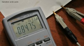
I've tried coil attached with super glue only on one side. Too much work but quite loud. I prefer tape or conductive acrylics. Usually you can buy with E-05 Ohm*meter range for repairs but I've found E-07, 100g for 60 Euro. But these found in a hardware shop won't polymerize at room temperature. They need a heat...
For quick prototyping elastomer+alu is fine. Have you tried carbon fiber? Speed of sound is high enough but thickness...
Hehe you know my neos have bent the aluminium trusses so imagine 2m tall transducer
I've tried coil attached with super glue only on one side. Too much work but quite loud. I prefer tape or conductive acrylics. Usually you can buy with E-05 Ohm*meter range for repairs but I've found E-07, 100g for 60 Euro. But these found in a hardware shop won't polymerize at room temperature. They need a heat...
For quick prototyping elastomer+alu is fine. Have you tried carbon fiber? Speed of sound is high enough but thickness...
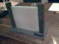
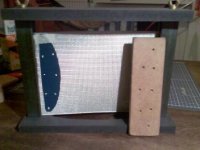
Hi,
magnets are not mounted yet. But you are right, magnetic
gap will be quite large, around 4mm.
I want enough space for experimenting with different
kinds of bondings between front/rear diaphragm and
voice coils. This model is not supposed to establish an
efficiency record.
When the kind of bonding is settled, i can use a narrower
gap later on.
Best Oliver
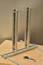
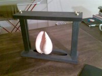
Hi,
blue piece in the middle is the winding form.
The cover piece has same size as the "table" and
is removed for the photo.
Blue piece has same thickness as the wire. Table and
cover force the wire to wind up in one plane.
Winding bench and winding form are coated with wax
before winding.
Bench parts are put together with screws before winding.
Glue is applied into the slots. Wire takes glue when wound
around the winding form.
Not easy i want to tell you ...
Best
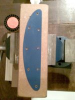
Hi,
yes the spiral coil has wire thickness.
The uncurved part is inserted upright into the
magnetic gap.
The curved part is to get current out of the
magnetic field, so current flows through the
field in one direction only.
4 coils are used. Each of the 2 diaphragms
has a pair of conducting layers to be driven
from both the left and the right edge.
2 coils glued flat to the inner side of front diaphragm.
2 coils glued flat to the inner side of rear diaphragm.
Uncurved part of the coil inserted into the magnetic gap.
Curved part outside the magnetic gap.
All 4 coils glued to the inner sides of the
diaphragms, they are invisible when device
is mounted.
Diaphragm acts as heat sink for the coils.
Coils act as damping elements for the diaphragm as
a secondary function.
Resin used to bond layers of the coils and the
copper itself are somewhat plastic to provide inner
damping of diapragms.
This is my current plan ...
- Status
- This old topic is closed. If you want to reopen this topic, contact a moderator using the "Report Post" button.
- Home
- Loudspeakers
- Planars & Exotics
- Sketch For Bending Transducer (Prototype already built)