Hi Bigun
If you have a transformer that has two separate HT windings, it works a charm. I happen to have a few transformers like this.
To make it work well without LW noise cancellation takes some PSU considerations as well. Some SS technology can creep into it, and I don’t want to upset the original poster...
My current 2a3 amp therefore does not use this topology, but I did breadboard it. Maybe it will get tried again soon?")
If you have a transformer that has two separate HT windings, it works a charm. I happen to have a few transformers like this.
To make it work well without LW noise cancellation takes some PSU considerations as well. Some SS technology can creep into it, and I don’t want to upset the original poster...
My current 2a3 amp therefore does not use this topology, but I did breadboard it. Maybe it will get tried again soon?
Member
Joined 2009
Paid Member
I'd rather have the simplicity of one supply than double up on all those psu parts for the sake of one resistor. And of course with stacked supplies you just swap one capacitor for another. It also makes it difficult, if not impossible, to use L-W noise cancellation.
You can do it with a single supply, take the first two stages of the amplifier at post #75 for example. Further, the plate voltage of the input tube is held at constant voltage, and all one needs then is a low impedance fixed reference shunt - and the voltage between the two is fixed then, as so would the bias of the second, or output tube.. just that shunt needs to accommodate Ip of the second tube, plus whatever is sent through it from the first stage.
This goes some way to addressing what Palustris is mentioning, with low value impedance of the output cathode wrt signal common, you can parallel VR tubes and it does good things for the (unfortunately) non-linear impedance, but the IME the current sharing is not equal, but so long as it is below Imax for the VR, I cant see a problem with it.
Hanze
Last edited:
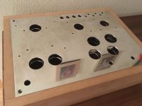
I used to think my breadboarding was a good idea, but nothing every got finished if you know what I mean !
At some time you need to go that step further and figure out the layout. Then you can build the chassis, top plate, etc..
Attachments

Last edited:
>> but I did breadboard it <<
me too
At the time, the sound was good, but I didn't have a good solution for the input/driver power supply. Basically, I wasn't happy with how to manage the PSU noise. The L-W noise cancelling works surprisingly well in the more 'traditional' build.
Btw - what size plate choke did you use for L3?
Last edited:
At the time, the sound was good, but I didn't have a good solution for the input/driver power supply. Basically, I wasn't happy with how to manage the PSU noise. The L-W noise cancelling works surprisingly well in the more 'traditional' build.
How about a pentode current source instead of a plate choke? Can then use L-W noise cancelling:
How do I design a pentode constant current source plate load?
Sheldon
Btw - what size plate choke did you use for L3?
No one. I did not get it yet.
Such an amplifier has a small THD, but it tends to have a high IMD. Without a good lab measure equipments, I would not dare to do it.
Nice Chassis work with Tango OPT
I have truck loads of ISO - Tango iron
NP Acoustics and Electra-Print
I have custom made M3 Double C core and Amorphous cores
At the Queensland Audio club will ask to do comparisons between Electra-Print M19 and M3 Double C core & GOSS soon same drivers and same custom made Toroidal Power supplies
Amorphous is essentially M19 steel in powder form heated to extremely high temperatures then cooled very quickly to create a very random non uniform crystalyne structure.
So we already get our own inbuilt airgap and iron with very low loss suitable for high freq power supplies .
It is great for mid range and high freq ,is not uniform or stable across the freq band with an inductive load , ie a speaker is applied and has very poor bass response without large chunks of Iron , typically -2dB at 20Hz is a good as it gets , and most manufacturers do not measure the transformers in any active amplifier but (Rp=Zp, -2dB) so in effect once you get the piece of iron into an active circuit about 50% of the claimed high end performance vanishes into the great abyss.
I have seen some manufacturers of SE OPT claim 7-151,000 Hz at -3db , this will not occur in a SE amp at 1 watt of full power , smoke and mirrors not even close to this
We hear 20Hz to 20Khz maybe a few a bit more in either direction depending on genetics but normally over time you maybe lucky to get to 15-18Khz
So if you can achieve in your SE amp 20Hz to 20kHz at .5dB or -1dB and 10Hz-40Khz -3dB or 50Khz -4to -5db at 1 watt or better still full power you in essence have reached close to known audio nervana for a SE tube amp no feedback
Normal CD's 16bit/44.1khz) hit the brick wall at 20.5kHz thats why Wadia developed the Digimaster filter to gradually roll off over 17-18 kHz .
Sure we hear over tones or harmonics back down the spectrum from 50 kHz or more that gives an impression of air or space but that is as good as it gets .
So don't sweat it over published manufactures data or exotic metal a bog standard EI M19 or M6 will take you there if it cleverly wound with bi or triflar layering .
The exotics will give you a really nice clear mid range and top end with pretty good base and Lowther lovers will enjoy them , and those with compression drivers and if you use a ton of exotic metal you might get the bass down to 20hz -1db but not the even response of M6 or M19 steel across the freq range with an inductive load at high power levels.
Subjectively i like the sound of exotic metals for human voice and small ensembles ,
and prefer M19 for bass slam and monitor grade amplifiers and M6 or M3 GOSS for full range orchestral music and load rock with lots of dynamics
There's life above 20 kilohertz! A survey of musical instrument spectra to 102.4 kHz - over tones - harmonics
Metglas® is an amorphous metal, Amorphous metals do not have crystalline structure like other magnetic materials. All the atoms in an amorphous metal are randomly arranged, thus giving it a higher resistivity (about three times) value than that for crystalline counterparts. Amorphous alloys are prepared by cooling the melt at about million degrees per second. This fast cooling does not give the atoms enough time to rearrange into stable crystalline form. As a result one gets metastable amorphous structure. Because of the absence of crystalline structure amorphous alloys are magnetically soft (lower coercivity, lower core loss, higher permeability). High resistivity gives lower loss at higher frequencies. The losses are among the lowest of any known magnetic materials.
How about a pentode current source instead of a plate choke? Can then use L-W noise cancelling:
How do I design a pentode constant current source plate load?
Sheldon
Hi Sheldon. Good suggestion! The 'upper' B+ will need to be higher than for the version with the plate choke... and maybe a solid state solution (CCS) would be less noisy (heresy of course, and not along the wishes of the original poster).
I have seen some manufacturers of SE OPT claim 7-151,000 Hz at -3db , this will not occur in a SE amp at 1 watt of full power , smoke and mirrors not even close to this
Specifications are sometimes cleverly "stretched".
When you take a close look at the frequency curve of your example, it is obvious that it includes the first resonance.
The real curve starts falling at about 30 kHz.
Member
Joined 2009
Paid Member
Hi Sheldon. Good suggestion! The 'upper' B+ will need to be higher than for the version with the plate choke... and maybe a solid state solution (CCS) would be less noisy (heresy of course, and not along the wishes of the original poster).
I don't see how the Pentode works that well as a CCS plate load for another tube whilst providing a high a.c. impedance - the screen of the pentode is fed by a resistor from B+ and is bypassed to the cathode with a capacitor - so at a.c. the impedance of this R + C string will be in parallel to the pentode and 'spoil' the high impedance it ????
Yes.
DC 300B just for example. So simple so good.
Thanks very much for this schematic pictured in message #79. So simple is correct, and this really is what I have been attempting to come up with by myself, but was fixated on providing a negative supply for the driver.
Member
Joined 2009
Paid Member
Perhaps mentioned already - but there is a nice write up here: Calculating DC coupled Single Ended Valve Amplifiers - Part #1
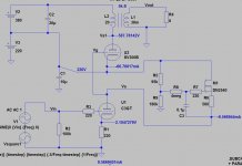
Hi RajkoM. Just to explain things a bit... you have 66.7mA on the cathode of the 300b, but the CCS only draws 9.5mA off it. The gyrator divider only draws 0.8mA.
Ok, so I would be tempted to cascode this CCS with a 2nd cn2540, and might use a different gyrator (I have been experimenting with a few). Also maybe you need to increase R8, but maybe not...
So, the question that one might want to ask is where does the rest of that 300b current flow?
Kind regards
Ok, so I would be tempted to cascode this CCS with a 2nd cn2540, and might use a different gyrator (I have been experimenting with a few). Also maybe you need to increase R8, but maybe not...
So, the question that one might want to ask is where does the rest of that 300b current flow?
Kind regards- Status
- This old topic is closed. If you want to reopen this topic, contact a moderator using the "Report Post" button.
- Home
- Amplifiers
- Tubes / Valves
- Single Ended 2A3/6A3/6B4G DC coupled & Transformer choices