Again I would not use a 6SF5 with a plate choke
I have used a 5842/WE417A with a plate choke from Electra - Print with good success
However the trend toward VHF - SHF driver tubes leaves the path open to occilations ,the need for short lead grid stoppers and unwanted interface
WE 717A E180F E280F and family of tubes can run away and occilate quite easily so most folk stick to 6SN7 6SL7 5687 etc for ease of operation and lineararity
i use a 8233 in triode mode ( mu30 RP 600R) with a 60H choke direct coupled to a 2A3 no problem of limited bass or miller capacitance")
E55L (8233) is a great choice. It will obviously work well choke loaded. I assume you have sensitive enough speakers.
Did you have a separate B+ supply for it?
Last edited:
Again I would not use a 6SF5 with a plate choke
I have used a 5842/WE417A with a plate choke from Electra - Print with good success
However the trend toward VHF - SHF driver tubes leaves the path open to occilations ,the need for short lead grid stoppers and unwanted interface
WE 717A E180F E280F and family of tubes can run away and occilate quite easily so most folk stick to 6SN7 6SL7 5687 etc for ease of operation and lineararity
I have personally used E180F, E280F, and a few others in triode. I don't like to mention them all since it tends to push prices up.
Anyway, I never had them oscillate. I never even had problems of microphony that some nay-sayers sometimes mention. Keeping the grid stopper close to the pin is just good practice. It's not hard to do.
Maybe if you are considering E810F, a few cheap ferrite eads will come in handy, but its really not that hard. Oops... I should not mention that one.
I can easily build an amplifier with 6SN7 or 6SL7 for you that will oscillate. Valves/Tubes love to oscillate.
Last edited:
E55L (8233) is a great choice. It will obviously work well choke loaded. I assume you have sensitive enough speakers.
Did you have a separate B+ supply for it?
yes i use it with horns , no separate B+ the choke of the driver is feeded by the power tube cathode ( DRD schematic)
but to be honest a 2A3 amplifier can sound as good with a small 6NP6 triode , or a 717A penthode like the yamamoto 's
it"s difficult to make a bad one..
Last edited:
Member
Joined 2009
Paid Member
but to be honest a 2A3 amplifier can sound as good with a small 6NP6 triode
Did you mean 6N6P? - this is not just any old triode, a rather powerful dual triode by any measure although gain is a bit low for a two-stage amp.
The US Airforce used ferite beads for years with HF/SHF tube grids
I do have STS 5A/170K - 6688- E180F which i quite like in triode , but i run 150v/ 9.1k WW Mills on the Plate rather than the WW Dale 10K on the plate 160v
They are smooth and clear and at 15mA on the plate can drive most tube grids quite well
I do have STS 5A/170K - 6688- E180F which i quite like in triode , but i run 150v/ 9.1k WW Mills on the Plate rather than the WW Dale 10K on the plate 160v
They are smooth and clear and at 15mA on the plate can drive most tube grids quite well
Hi Hanze
If you are looking at the output impendance, it depends whether or not you bypass the cathode resistor.
if you are bypassing the cathode or using LED, or negative grid bias, etc then you can pretty much assume:
Output impedance = ra || Rp
So if you properly by-pass the cathode, then you don't really need to take it into account for the output impedance calculation...
However if you do not bypass the cathode, then:
Output impedance = ra' || Rp
where ra'(unbypassed Rk) = ra + (mu + 1)*Rk
Still, for unbypassed cathode adding (mu+1)*Rk is not always sooo bad - don't forget that it is in parallel with the load. I kind of like the un by-passed stage for a variety of reasons. Yes, there is negative feedback and less gain and higher ra though. Those things are obvious.
Also, if you are using a CCS or gyrator, and DC connect right off the plate, Rp is a huge effective value. Of course it can vary over frequency depending on the CCS devices and implementation. Life gets complicated again... But let's not let that distraction get in our way today either.
So, if I understand what you are doing above correctly, the drive signal is 150mV AC RMS? A tiny signal for sure. Mic or phono perhaps?
For what you have above I would consider even trying 20mA and an Rk of 20 ohms if the plate volts is not an issue for your application. Or maybe 15mA and 25 ohms... If the cathode is bypassed I would just go for a higher bias value.
Sorry for the late reply, no disrespect intended.
mV input signal, yes.. but also its a -ve current signal so a small value 'grid leak' resistor actually biases the stage, and it will come down to the value of Rk to decide drive impedance from the plate. 10R is about as low as I can think to go, on account of at least having a 'cathode stopper' to help prevent oscillations, its stable up to the limit of my function generator and I'd like to keep it that way.
It was an oversight on my behalf that a measly 42R in the cathode circuit (Rk) adds ~3250 ohms to the drive impedance when CCS loaded.
Having a few issues with CCS loads and the 'mu-output', Pimm design is ok with CR (RC) but not (CR//L) loads, as it rings like a banshee, but is completely stable when unloaded (the mu output), so it is fine as CCS.. just need to keep Rk small as possible (and avoid Ck).. should be fine...
Could try (and would) one of Ale's CCS first: Hi Ale, your email bounces back - but all to say thanks for the tips and I will try this plate direct connection firstly.
Wondering the impact of biasing at now -200mV and 10mA with horizontal load, Vin is ~120mVp-p, so 80mV headroom and such low (30R) grid lead that Ig is not a problem.. it doesnt look so linear down there on the data sheet, but with very minimal swing, perhaps it does not matter so much when taken into context.
Anyway, I digress - please carry on.
Hanze.
Last edited:
SS devices can work like a choke too for direct coupling. That was the point I was trying to make.
They have certain advantages over traditional chokes as well. Also, its worth noting that especially for single-ended amplifiers, the power supply is fully in the loop.
So if you are using a maita regulator, you already have SS in your audio signal. Nothing wrong with that though.
Here‘s a cool idea that I am tempted to try out:
1. Use a “statistical regulator” power supply for the input/driver stage. This will set a really quiet, stable power supply.
2. Use a plate choke to load your input/driver. Bias as you prefer. A triode strapped pentode can work well here, as discussed.
3. You might be able to transformer couple. This can allow you to set up negative grid bias, a lower B+ and a cathode that is close to ground. No hassle with cathode bias...
3a. Or direct couple and use cathode bias.
4. Use a traditional LCLC supply for your 2a3, 300b etc.
The “statistical regulator” can be done with valves/tubes for the purists in the crowd.
Ian
Hi Kiwi member , i should have made the tread clearer when I started the thread , I will now , no SS stuff on the plate of tubes just Iron please for this thread !
If folk want to start a thread on SS stuff then please go ahead am sure there are plenty of folk out there who want to blend technologies out there
If folk want to start a thread on SS stuff then please go ahead am sure there are plenty of folk out there who want to blend technologies out there
no worries.
Like I suggest in post 71, you can do it all with valves/tubes.
imho, if you don't want to use the monkey method then a separate power supply for the input/driver stage is an option.
The "statistical regulator" on the input/driver would be a good way to achieve a very stable reference, and could be done with valves/tubes as well. I would think of using a pentode/triode cascode, and maybe instead of a zener stack (as Morgan Jones suggests) one could try two 0C2 VR's in series.
There will likely be some loss over the plate choke, but the voltage should be in some decent range for direct coupling... Again, this is just an idea.
Or would a zener stack be allowed? Its just for voltage reference and not "on the plate".
The reason I would go to all this effort is to get that firm DC grid reference and as quiet, yet dynamically responsive supply as possible.
Last edited:
Depends on what you are trying to do..
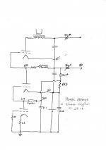
I agree with the other poster about SS devices offering some advantage. Say for example this direct coupled and choke loaded amplifier .. you can see that the whole thing would be lost without the one very unique function that the gyrator can provide... actually - it provides another function as well. Given (Ales) circuit, you can easily limit the LF to the amplifier, all to say that bi-amping - even if that is running a subwoofer to upper limit of 80Hz and limiting LF to the main amplifier itself, can be done on the gyrator board, very easily and NOT in the signals pathway.
To Soulmerchant: Thanks. -3dB at 40kHz with 10R Rk and D3a with CCS load parafeed into TX-102 v3 400H autoformer, just down from flat to (-0.91dB) 20kHz. For multi-bit DAC, I consider this like organic LP filter
Anyway, food for thought.. and back to DC circuits, here is my amplifier design, developed in conjunction with a friend - happy to share it.. six Coleman regulators, six 1930's tubes, so inefficient on every level. Yep, just like me !!
The SS device could be substituted by an inductive plate load, but it wouldnt work the same way - sorry mate, this is an edit, I added this after I see you 'changed the rules' about loading schemes. This post fully meets with the criteria as set out by the original post, otherwise you might start a new thread. It may offer some insight into how to implement the inductive loads, which you may or may not sell as retail, to help others who do not wish to be confined to a two stage design.
Hanze
Attachments
Last edited:
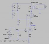
There has been very good discussion about the driver stage and direct coupling, but there has been no discussion about the output stage that I can see. While I have built the monkey/drd several times I am now listening to an amp built with the topology included on the right in message #1. That is to say, employing a big cathode resistor on the 2A3 to bias the 2A3 relative to the driver. Normally, this resistor can be 2.5k ohms to 3k ohms depending on the driver tube's plate voltage requirement. This to me is just plain inelegant engineering. So I would like to consider more elegant engineering solutions to the big resistor. For instance has anyone tried a CCS or voltage regulator tube under the 2A3 cathode. Are there any other solutions to raise the cathode voltage of the 2A3 to match the driver?
Member
Joined 2009
Paid Member
Member
Joined 2009
Paid Member
Stacked power supplies allow DC coupling and avoidance of the big resistor on the output valve.
t
I'd rather have the simplicity of one supply than double up on all those psu parts for the sake of one resistor. And of course with stacked supplies you just swap one capacitor for another. It also makes it difficult, if not impossible, to use L-W noise cancellation.
- Status
- This old topic is closed. If you want to reopen this topic, contact a moderator using the "Report Post" button.
- Home
- Amplifiers
- Tubes / Valves
- Single Ended 2A3/6A3/6B4G DC coupled & Transformer choices