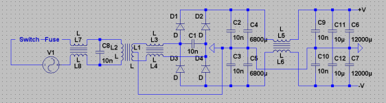
I would separate L5 from L6. There are some suitable 6A
power supply chokes in your box shipping today...
I don't see your transformer couplings K1 etc.. Stated
anywhere in that screenshot.
That said, I don't see the purpose of "K3 L3 L4 1" as this
coupling is already assured by K2. Reading K's left to right.
Everything from the wall up to but not including the diode
bridge, already encapsulated in a metal brick with IEC (PC
power socket), switch, and fuse. This is also in the box.
Last edited:
There are no coupling commands. If the inductors are joined then they are coupled. I didn't simulate this. Why separate L5 and L6? I thought this improved line regulation.
While looking out the bus window I spotted a place called DTL electronics... They just opened up 2 months ago! I went inside. Low and behold, a Tek 465B was staring me in the face! That's sitting beside me now (they sold it ultra-cheap since it has some... problems). So now I have my 561B for 10uV precision, and then a dual trace scope for normal measurements up to 20MHz!
You should have seen their faces when I asked them to repair my 561B vertical plugin. They will do it for a standard fee. They set up their own business after getting laid off by TI, so I'm going to send as much business their way as I can muster. As far as I know, no one knows they exist (why do small businesses like this never advertise!?).
- keantoken
Last edited:
Find your local HAM radio club. You can milk that angle for all sorts of free equipment.
We talking WW2 dudes ready to keel over, with nobody to appreciate their junk piles.
You might have to put up with earning a Technician class license (dead simple) and
helping with some of their public service tomfoolery. But I can about guarantee you
will have more books, tubes, and vintage test gear than you can shake a stick at.
Besides, one you get that licence, you can legally operate the microwave oven
with the door off (not advised). As long as you aren't jamming or cooking anyone,
nor playing MP3s, unless its the space shuttle... Or something like that...
Last edited:
What's wrong with the 465B? Can they fix it?
What is a M.O.A.N Technical Adviser and Recruiter?
The scope lights up fine, and might or might not display a trace when you power it up. If not, it's just a dot or two sitting in place on the screen. Then after a while, the horizontal deflection will go out (if it worked when you turned it on) shortly followed by the whole thing powering off (presumably by self-shutoff/overload protection).
I actually got out the door before I realized I could pay them to fix it, after asking them what it would cost to fix my Ancient Anchor, to boot. However, they were talking about replacing the internal board modules, which would take much more $$ than just replacing the few burnt resistors... Since I know exactly what's wrong with my 561B, I'm more likely not to be had.
Will do Ken. I will go to that page again and get someone's Email address.
- keantoken
M.O.A.N.
Men Of Action uNite
Sawrey, Ken, wanna join?

Information:
http://www.diyaudio.com/forums/member.php?u=62223
- keantoken
Men Of Action uNite
Sawrey, Ken, wanna join?
Information:
http://www.diyaudio.com/forums/member.php?u=62223
- keantoken
Don't connect any big caps to those power supplies till you have measured the
actual polarity of the outputs. I don't think those supplies are well marked, and
the spec sheet shows entirely different style connectors.
Big caps will create a serious mess if mis-oriented. Considering unknown time on
the shelf and in the warehouse, you might even want to re-form the dielectric
barrier on a lower, safer voltage, before allowing them to charge fully.
I'd also slap a bleeder resistor across each, so they will be safe for screwdrivers
in a known RC time constant. Even if the circuit they are/were in fails to bleed
them due to blown fuse or other open circuit...
Don't connect any big caps to those power supplies till you have measured the
actual polarity of the outputs. I don't think those supplies are well marked, and
the spec sheet shows entirely different style connectors.
Big caps will create a serious mess if mis-oriented. Considering unknown time on
the shelf and in the warehouse, you might even want to re-form the dielectric
barrier on a lower, safer voltage, before allowing them to charge fully.
I'd also slap a bleeder resistor across each, so they will be safe for screwdrivers
in a known RC time constant. Even if the circuit they are/were in fails to bleed
them due to blown fuse or other open circuit...
Do you mean the switchers you're sending?
I powered up both of those amps and nothing bad happened, so the caps should at least be good at the amp voltages. How would I reform them? I assume I can simply apply a constant current and let them be for say, a day or two (one of those CCS diodes would be perfect for this)?
What size resistor should I use for bleeders? I don't have anything more than 1/4W types, though I could go to Radioshack and get a specific value.
- keantoken
Last edited:
Sending? Sent. You havn't opened the 1st box yet??
You won't be needing no resistors from the shack.
I speak of the 68,000uF halfsize coke cans... No telling
how old those might or might not be? So take care the
first time you apply power. They can release enormous
energy, more than enough to injure your eyes or hands
if one decides to pop... Treat like an M80 firecracker.
Bleeder can be small wattage, 1/8W fine. We speak of
100K to a Meg across the terminals. No large currents.
Just a path of last resort that will eventually discharge
the cap to make it safe for screwdrivers.
Sending? Sent. You havn't opened the 1st box yet??
There are... Verbose penalties... If we disturb his sabbath. I haven't been able to contact him over the second package because he refuses to answer his phone.
Not my first choice as alternate address, maybe you understand why. D:
My uncle's motherboard bit the dust when he tried to upgrade the BIOS for a better processor. If I can't somehow revive it, I'll use it for parts if I can.
- keantoken
No no... Don't risk any verbose penalties...
If a 2nd box is just too politically incorrect,
don't give him reason to hold back whats
allready been sent.
We will simply find a different mule.
1st box had the majority of the best stuff.
There are gems in the 2nd box, but fewer,
and further between. And not yet ready
to be shipped anyway.
Those 6inch whizzer have been measured.
Definately no Fostex... Fs way too high
for full range. But probably work fine for
mid/high if rolled well above the enormous
Q peak.
They sound better than they measure,
But definately not like the real thing.
What fills the Boston holes right now?
I have some coaxials that might cover
wider bandwidth, but are only 5 inch...
Check if that BIOS can be JTAG'd?
Like a 10 pin header, semi-standard
for that purpose... Use a different PC
with parallel printer port and DIY cable
to shove the BIOS to the one whats
lost its marbles.
Last edited:
I'm sure there will be no problem, and I'm sure I'll get the boxes even if some verbosity takes place.
The Boston A40 boxes are filled with 4 ohm Scosche car speakers. 200W I think (as if I'd ever need that). They are advertised as having Kevlar composite woven cones, and for having smooth response. I bought them from Walmart for $80 because they were most certainly the best available... Anything else sounded exactly like what they were made of: plastic. The tweaters that came with the A40 are still there and to my knowledge still work (the magnet fell off of one though and I never saw any of that Ferrofluid stuff), but they are not in use and I am using the tweaters that came with the speakers.
- keantoken
http://www.parts-express.com/pe/showdetl.cfm?Partnumber=290-023
Several reviewers seem to have used these Pioneers as replacement
drivers in your same box. Certainly cheaper than $80 a pair...
I don't know what makes best replacement for the fluidless tweeter?
The Bostons I use at work, have huge heatsinks on the backs of the
tweeters, cooled by the tuned port. Not the same model as yours.
Last edited:
http://www.parts-express.com/pe/showdetl.cfm?Partnumber=264-840
Does this Tang Band look anything like the Boston tweeter?
Does this Tang Band look anything like the Boston tweeter?
http://www.parts-express.com/pe/showdetl.cfm?Partnumber=264-840
Does this Tang Band look anything like the Boston tweeter?
Not at all.
Here for reference...
http://www.diyaudio.com/forums/showthread.php?p=1922974
- keantoken
Also, my speakers are A40 Series II, not originals.
I have this dream of getting some 1" slabs of tabletop granite custom cut and building myself some nice looking bookshelf speakers. The front will be made of some transparent material, and the inside will be coated with sound-absorbing foam pyramids... It should look cool, though others have advised me to just stuff them with fiberglass or a common sound absorbing material.
- keantoken
Last edited:
- Status
- This old topic is closed. If you want to reopen this topic, contact a moderator using the "Report Post" button.
- Home
- Amplifiers
- Solid State
- Simulation Analysis of several unique Allison-based output stages.