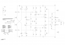
Here the Allison is used to bias the drivers and provide bias voltage to the output BJTs. This is one good place for it. However P1 shunts the Allison by a potentially arbitrary amount depending on what voltage is needed to bias the outputs. It could be running as low as 100uA. Clearly this design is using it mainly as a bias stabilizer and not much else.
Good point, but we don't know where the pot is typically set.
Your point brought C5 also to my attention and that certainly
shunts the HF feedback.
I have to look up Allison's article but several here have commented
that they think he intended for it to just be a bias circuit and not for
error correction. The question is then who first noticed that it can be
used for EC.
Last edited:
The fact that this circuit does not have a linear output at a fixed impedance, and does not take input from the feedback emitters makes it fairly unlike the Allison. Of course to be sure we would have to dig up the original references and ponder the exact definition given to the Allison circuit (if there is one), at which point it would be rather academic.
It is close enough I always just called it an Allison driver scheme. Others called it a CMCL or Common mode control loop, which is a more general name that can apply to any active bias circuit.
Generally if you refer to it as an Allison type circuit you would do so to emphasize the chief features of the Allison; it's linear output and fixed output impedance. In this case neither of those features are taken advantage of. So all that is left is the resemblance of the schematic to an Allison schematic. Which is still a valid comparison, and topologies are discussed this way all the time, but perhaps it is better communication to use a name that is more pertinent to your goals.
- Status
- This old topic is closed. If you want to reopen this topic, contact a moderator using the "Report Post" button.
