At 10KHz, which I think is a frequency representing compensation quality, distortion increases from .031% to .064%. I don't know whether output drivers will bring these figures closer. Distortion at 1KHz changes only barely from .0305 to .31. This is at 12V into 6R.
That sounds good to me, but right now I am invested in my own design.
I found 100R resistors in series with each Miller cap damped a resonance around 50MHz; could be much worse in real life.
OK, many thanks for the info keantoken.
Wish you the best outcome from your design, regards.
")
Last edited:
I found 100R resistors in series with each Miller cap damped a resonance around 50MHz; could be much worse in real life.
Or non existant, sims are far from perfect. Another case, it shows any triple EF outputstage as being unstable, but in real life a couple of million amps have been sold using it and perfectly stable.

I didn't like the sound of 100R in series with miller cap in my fetzilla but one cap with 100R and another in parallel without sounded fine.
I don't think KT is suggesting a tendency for oscillation rather just a tendency for low level ringing that spoils the sound.
This tendency once again being in sims, the question is if they are really there in real life.
This must be built and tested for, no point in speculating, it is not worth the time scrutinizing simulation when it is faster to solve the problem in a real prototype.
Ringing and oscillation can be virtually equivalent, if it's a resonance constantly perturbed, or if the oscillation is only sustained on negative half-waves or 5A excursions. It is best not to have any of either when it can be helped.
Ringing and oscillation can be virtually equivalent, if it's a resonance constantly perturbed, or if the oscillation is only sustained on negative half-waves or 5A excursions. It is best not to have any of either when it can be helped.
Last edited:
This tendency once again being in sims, the question is if they are really there in real life.
No, you misunderstand me I was talking about what I heard when I tried it.
In simulation the 100R is excellent - in real life it makes the amp sound lifeless.
Inverting SSA
There is no way out for the purpose mentioned earlier the amp must be inverting.
Anyway with the feedback system shown earlier it has now a current input and a current output . But does this schematic make sense ? Of course it can be simulated.
There is no way out for the purpose mentioned earlier the amp must be inverting.
Anyway with the feedback system shown earlier it has now a current input and a current output . But does this schematic make sense ? Of course it can be simulated.
Attachments
Distortion of the shunt compensation can be brought down considerably by applying the entire Symasym compensation scheme, after you have added drivers.
This Symasym compensation scheme interests me. Keantoken, it would be very nice if you can elaborate it in a short form. Many thanks.
Hi igor0203
Well the amp is fully functional, playing music nicely, but it is still in R&D phase, so some more improvements will be tested before to go to conclusion of the project and say, this is the final SSA version.
What's happening now is an upgrade for CCS current injectors to SSA feedback bridge, since it was realized that the distortion spectrum is much more clearer with the use of high performance CCSs. And these are ready to build and installed into the amps. Both positive and negative CCSs are located on PCB size 30 x 45 mm (attached) and will be soldered to main PCB as add-on module. Will look quite professionally I tell you.
Any chance of listening this beast?

Last edited:
This Symasym compensation scheme interests me. Keantoken, it would be very nice if you can elaborate it in a short form. Many thanks.
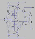
Here it is. The 100pF cap, not the one at the input, is the shunt compensation. It is analogous to Ccomp in my schematic. What isn't immediately apparent is Rcomp, that always comes with shunt compensation. If this cap is deleted, a network of 620p+220R can be placed between the VAS bases to the same effect. Only then, the nonlinear Vbe is imposed across it which might lead to more distortion. The advantage of Mike's approach is that a smaller capacitor can be used, and this arrangement causes less distortion. PSRR is increased, but the frontend rails are RC'd anyways.
The trickyest thing about this amp is where Rcomp has gone. That was the biggest confusion for me, and the compensation of this amp does not make much sense until you've studied Shunt compensation in detail. The R in series with Ccomp sets the amp open-loop gain to a lower value at the frequency needing compensation. In Symasym this is not needed because the other half of the VAS is not compensated. So the uncompensated half of the VAS provides the gain that would otherwise be conserved by adding Rcomp.
The other important part of this compensation scheme is the 330p caps. These caps provide the gain roll-off, whereas the RC shunt just steps the gain down. The best economy of compensation and distortion is achieved when the RC shunt is made smallest by using larger 330p caps. However you can't make them too large or you get RFI issues, like Miller compensation. I prefer to instead make these caps as small as possible while still providing the large reduction in distortion resulting in a smaller RC shunt. This is because in my tests, the 330p caps detracted from realism and soundstage depth. I was only on one prototype though.
Finally, the SSA can be reworked to mimic the Symasym scheme pretty closely, because like Symasym it has two VAS's. However this doesn't work well unless we lower the SSA's open-loop gain significantly. Rather, it works best to keep my previous compensation scheme and simply add a capacitor to the VAS output like the symasym. See my schematics.
With this compensation scheme, all harmonics are below -110db from the fundamental, at 12V, 10KHz into 6R.
If MikeB is not a genius, then he had a very happy accident.
Attachments
Homemodder, what I meant when I said "reworking" it to mimic Symasym, was to connect a cap across only one VAS, and leave the other VAS uncompensated, like the Symasym. It doesn't work though, because even at half open-loop gain the VAS output cap is not enough to stabilize it. So I've accepted the higher parts count. There may be other ways we can implement lop-sided compensation.
Phase lead can disguise the hump but it can't make it go away. It is nice to have a perfectly rounded square wave, but since learning about group delay I see that as somewhat superficial. It is good to keep peaking and response within bounds, but beyond that is superficial unless you're looking directly at group delay. A response may appear to be geometric, but if you look at the group delay it becomes painfully apparent where the corners went. Very simple amps, even if their distortion and speed specs are not great, tend have have more phase linearity (constant group delay=phase linear). This may be the technical appeal of TSSA. On the other hand, if phase-lead lowers distortion, then why not.
Phase lead can disguise the hump but it can't make it go away. It is nice to have a perfectly rounded square wave, but since learning about group delay I see that as somewhat superficial. It is good to keep peaking and response within bounds, but beyond that is superficial unless you're looking directly at group delay. A response may appear to be geometric, but if you look at the group delay it becomes painfully apparent where the corners went. Very simple amps, even if their distortion and speed specs are not great, tend have have more phase linearity (constant group delay=phase linear). This may be the technical appeal of TSSA. On the other hand, if phase-lead lowers distortion, then why not.
Last edited:
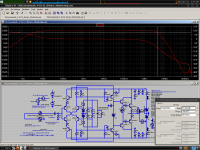
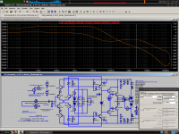
Also Homemodder, I see in your schematics that you use my old simulation command set. I apologize that this old version has an error in the sample calculation. The new version is attached, I use this "bench" to simulate all my amps, and I have had extremely few problems.
Attachments
In this case phase lead doesnt lower distortion, its the way I used in commercial version, at the time the reason was only because it sounded slightly better to me but later on the company informed that it displayed better square wave response and rise time with capacitive loads than with regular miller.
I obtained this command set from AndyC, (he later supplied another) from the old days (3 4 years back) with one of ostrippers amps. I havent a problem with it, results seem to be same as for the simplified spice commands. Ill try the new one, see what differences come up.
I obtained this command set from AndyC, (he later supplied another) from the old days (3 4 years back) with one of ostrippers amps. I havent a problem with it, results seem to be same as for the simplified spice commands. Ill try the new one, see what differences come up.
KT, your distortion decrease doesnt come much from the different compensation, its more due to the change to the input pair, what a coincidence, just this morning I played around with that scheme again (basically turn input pair with vas into a baxandall) but I remember all to well many years back I couldnt get it stable. Well now with simulators one can beat your head around and get it too work, yours looks it could.
Finally someone sees where the main distortion is coming from, the vas. Theres practically no voltage swing at the input pair, the contibution to THD there is next to nothing.
Finally someone sees where the main distortion is coming from, the vas. Theres practically no voltage swing at the input pair, the contibution to THD there is next to nothing.
Last edited:
Well, I do try to compare apples to apples. I was comparing different compensations with the same version, feedback buffers, drivers and all. I'm not concerned with static THD much, more with the IMD caused by compensation. Really all I'm doing is increasing open-loop bandwidth, without using Miller comp, which was my goal in the first place.
And I never said this compensation was an improvement over Miller, distortion wise, although it can about equal it with the VAS output cap. I care about this compensation because I thought it sounded better, and it has better RFI immunity.
I know that a cascoded VAS would be better, but that is not as intriguing, so I'll save it for when I'm through with comparisons, and want to upgrade the design.
Well, I do try to compare apples to apples. I was comparing different compensations with the same version, feedback buffers, drivers and all. I'm not concerned with static THD much, more with the IMD caused by compensation. Really all I'm doing is increasing open-loop bandwidth, without using Miller comp, which was my goal in the first place.
And I never said this compensation was an improvement over Miller, distortion wise, although it can about equal it with the VAS output cap. I care about this compensation because I thought it sounded better, and it has better RFI immunity.
I know that a cascoded VAS would be better, but that is not as intriguing, so I'll save it for when I'm through with comparisons, and want to upgrade the design.
KT, dont get me wrong, youre taking the right route
Just that you saw the possibilty of turning the input and vas combination into baxandall pair is brilliant, congratulations. It kicks vas distortion in the teeth. Its not really baxandall pair but has similar effect. Over the weekend I took out my old prototypes and removed some circuitry that raised loop gain, what was left gives me just 35db, what happens is that low frequency THD rises x5 (.001) but high frequency (20Khz) less than 1.2 (.0065). Open loop Fc now at near 30 Mhz. Was it worth raising the loop gain ??, Not in my case, there is very little difference to be heard. The very low THD requirement was a move dictated by market to show performance on paper.Using a zillion more parts to obtain just a little beter spec is not really worth it in the end youll find. Look at the latest design here, gone is the simple, and all that to achieve better THD and temp comp, in many cases you end up with a worse sounding amp in the end too. It can can all be done with half the complexity with clever circuitry, thats why that input stage scheme is brilliant if you can get it going. Try a prototype.
Btw what does those cascodes on the emitters of the input pair do ??
- Status
- This old topic is closed. If you want to reopen this topic, contact a moderator using the "Report Post" button.
- Home
- Amplifiers
- Solid State
- Simple Symetrical Amplifier